Synchronization of wireless transmitted MRI signals in MRI system

a wireless transmission and synchronization technology, applied in the field of mri, can solve the problems of cable transmission degrading the detected signal, affecting the reception of detected auxiliary signals by detector electronics, and affecting the synchronization of free induction decay signals

Active Publication Date: 2006-10-17
THE BOARD OF TRUSTEES OF THE LELAND STANFORD JUNIOR UNIV
View PDF5 Cites 81 Cited by
  • Summary
  • Abstract
  • Description
  • Claims
  • Application Information

AI Technical Summary

Benefits of technology

[0012]In accordance with the invention, a pilot signal is transmitted from the processing unit of a MRI system to the FID detector unit with the pilot signal being processed and modulated along with the FID signal for transmission back to the processing unit. The processing un...

Problems solved by technology

However, cable transmission can degrade the detected signal, and coaxial cables require the use of balans for signal coupling.
Further, cables present a contamination problem in interventional MRI which requires a sterilized coil.
Unfortunately, the detected auxiliary signal suffers fluctuations when received by the detector electronics due, in part, to the relatively high voltage pulses of the MRI pulse...

Method used


Image

  • Synchronization of wireless transmitted MRI signals in MRI system
  • Synchronization of wireless transmitted MRI signals in MRI system
  • Synchronization of wireless transmitted MRI signals in MRI system

Examples


Embodiment Construction

[0025]As above described, wireless transmission of MRI signals is complicated by the need to maintain full phase synchronization between the MRI scanner and a coil transponder. Any local oscillator phase or frequency errors must be eliminated.

[0026]Heretofore, the prior art has attempted to eliminate phase errors by applying an auxiliary or reference signal to control a local oscillator for the FID signal modulation. The detection electronics must robustly amplify this auxiliary signal which drives a phase locked frequency synthesizer as the local oscillator.

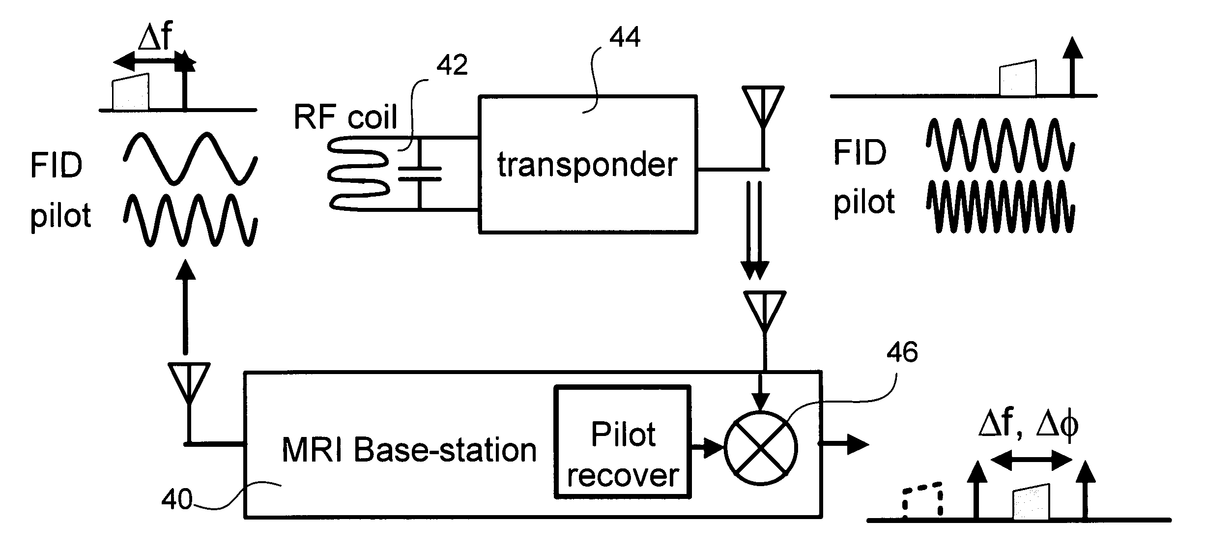
[0027]The present invention employs a pilot signal which can be transmitted from the processing unit to the signal detector during FID signal reception and which is processed and transmitted along with the detected FID signal back to the processing unit. With synchronous demodulation, one side band of the modulated carrier is received and processed. However, the processor unit can electronically lock to the pilot instead of the ...


PUM


Abstract

In a MRI system having a FID detector unit and a computer unit for processing FID signals, phase errors introduced into the FID signal at the detector unit are corrected at the computer unit by transmitting a pilot signal from the computer unit to the detector unit, processing the pilot unit along with a detected FID signal at the detector unit, transmitting the processed signals to the computer unit, obtaining the pilot signal and FID signal at the computer unit, and combining the pilot signal and the FID signal whereby phase errors cancel.

Description

GOVERNMENT RIGHTS[0001]To be determined.BACKGROUND OF THE INVENTION[0002]This invention relates generally to magnetic resonance imaging (MRI), and more particularly the invention relates to transmission and phase synchronization of a detected free induction decay (FID) signal to signal processing apparatus in a MRI system.[0003]Magnetic resonance imaging (MRI) requires placing an object to be imaged in a static magnetic field, exciting nuclear spins in the object within the magnetic field, and then detecting signals emitted by the excited spins as they precess within the magnetic field. Through the use of magnetic gradient and phase encoding of the excited magnetization, detected signals can be spatially localized in three dimensions.[0004]FIG. 1A is a perspective view partially in section illustrating conventional coil apparatus in an NMR imaging system, and FIGS. 1B–1D illustrate field gradients which can be produced in the apparatus of FIG. 1A. This apparatus is discussed by Hins...

Claims


Application Information

Patent Timeline
IPC IPC(8): G01V3/00
CPCG01R33/3621G01R33/3692
Inventor SCOTT, GREIG C.
Owner THE BOARD OF TRUSTEES OF THE LELAND STANFORD JUNIOR UNIV
Why Eureka
Try Eureka