Circuitry for providing overvoltage backdrive protection

a backdrive protection and circuit technology, applied in logic circuits, pulse techniques, reliability increasing modifications, etc., can solve problems such as gate oxide breakdown when the low-power module is powered down, device failure, and module using the lower power supply voltag

Inactive Publication Date: 2006-10-17
NAT SEMICON CORP
View PDF6 Cites 4 Cited by
  • Summary
  • Abstract
  • Description
  • Claims
  • Application Information

AI Technical Summary

Problems solved by technology

This difference in operating conditions may cause problems for the module using the lower power supply voltage, particularly if the modules are coupled by a common bus.
Another problem that occurs with modules operating under different power supply voltages is the potential for gate oxide breakdown when the low-power module is powered down (i.e., when the power supply is at 0 volts).
The maximum gate to back-gate voltage is 5.3 V. A +5.0 volt signal appearing on a common bus when the +3.3 volt module is powered down can create gate oxide voltages exceeding the 4.6 V level, leading to device failure.
However, when the invention disclosed in U.S. Pat. No. 5,555,149 is powered down, it provides no protection against gate oxide breakdown.

Method used


Image

  • Circuitry for providing overvoltage backdrive protection
  • Circuitry for providing overvoltage backdrive protection
  • Circuitry for providing overvoltage backdrive protection

Examples


Embodiment Construction

[0017]FIGS. 2A, 2B and 3, discussed below, and the various embodiments used to describe the principles of the present invention in this patent document are by way of illustration only and should not be construed in any way to limit the scope of the invention. Those skilled in the art will understand that the principles of the present invention may be implemented in any suitably arranged network interface card.

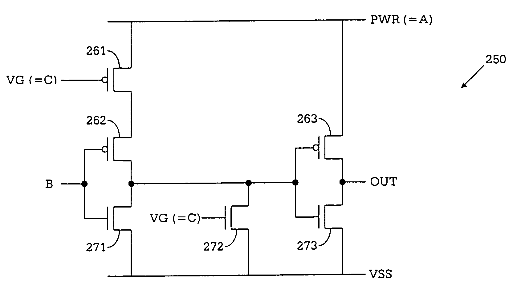
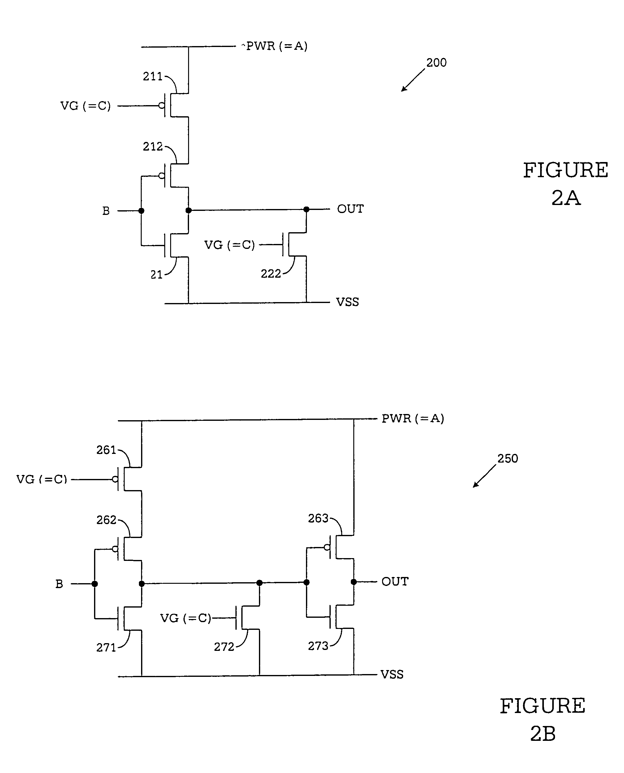
[0018]FIG. 2A illustrates NOR gate 200, which operates with output driver circuit 100 in FIG. 1 according to the principles of the present invention. NOR gate 200 comprises p-channel transistor 211, p-channel transistor 212, n-channel transistor 221 and n-channel transistor 222. Transistors 211, 212, 221 and 222 operate from the PWR-power rail and the VSS power rail. The PWR power rail of NOR gate 200 is connected to the source of p-channel transistor 211 and to node A in output driver circuit 100. The VSS power rail is coupled to ground (or another reference voltage) and to th...


PUM


Abstract

A logic gate for use in an electronic system comprising: i) a first component operating from a low voltage power supply rail; ii) a second component operating from a high voltage power supply rail; and iii) an over-voltage protection circuit that detects an over-voltage on an output pad of the first component and, in response to the detection generates from the over-voltage a generated power supply voltage and a generated reference signal. According to an advantageous embodiment of the present invention, the logic gate comprises a plurality of transistors, wherein the plurality of transistors are powered by the generated power-supply voltage and at least one of the plurality of transistors is turned ON and OFF by the generated reference signal.

Description

[0001]This application is a continuation of prior U.S. patent application Ser. No. 10 / 440,033 filed on May 16, 2003 is now a U.S. Pat. No. 6,906,553.TECHNICAL FIELD OF THE INVENTION[0002]The present invention is related to over-voltage protection and, in particular, to logic circuits operating from an output driver that prevents reverse charge leakage and gate oxide breakdown when the voltage on the driver output exceeds the driver internal power supply voltage or when the driver is powered down.BACKGROUND OF THE INVENTION[0003]Many modern electronic devices contain components that operate from different power supply voltages. For example, in a laptop computer, the data processor module may be powered by a +3.3 volt power supply while the disk drive(s) may be powered by a +5.0 volt power supply. This difference in operating conditions may cause problems for the module using the lower power supply voltage, particularly if the modules are coupled by a common bus. A condition known as ...

Claims


Application Information

Patent Timeline
Patent Type & Authority Patents(United States)
IPC IPC(8): H03K19/0185H03K19/003
CPCH03K19/00315
Inventor WERT, JOSEPH D.
Owner NAT SEMICON CORP
Why Eureka
Try Eureka