Automatic optical proximity correction (OPC) rule generation

Active Publication Date: 2006-10-17
ASML NETHERLANDS BV
View PDF13 Cites 15 Cited by
  • Summary
  • Abstract
  • Description
  • Claims
  • Application Information

AI Technical Summary

Benefits of technology

[0017]In an effort to solve the aforementioned needs, it is an object of the present invention to provide a method of generating a set of rules which allow for the automatic application of optical proximity correction techniques to a re

Problems solved by technology

These rules are set by processing and design limitations.
As the size of an integrated circuit is reduced and its density increases, however, the CD of its corresponding mask pattern approaches the resolution limit of the optical exposure tool.
This is in part due to the fact that OPC rules are not universal

Method used


Image

  • Automatic optical proximity correction (OPC) rule generation
  • Automatic optical proximity correction (OPC) rule generation
  • Automatic optical proximity correction (OPC) rule generation

Examples


Embodiment Construction

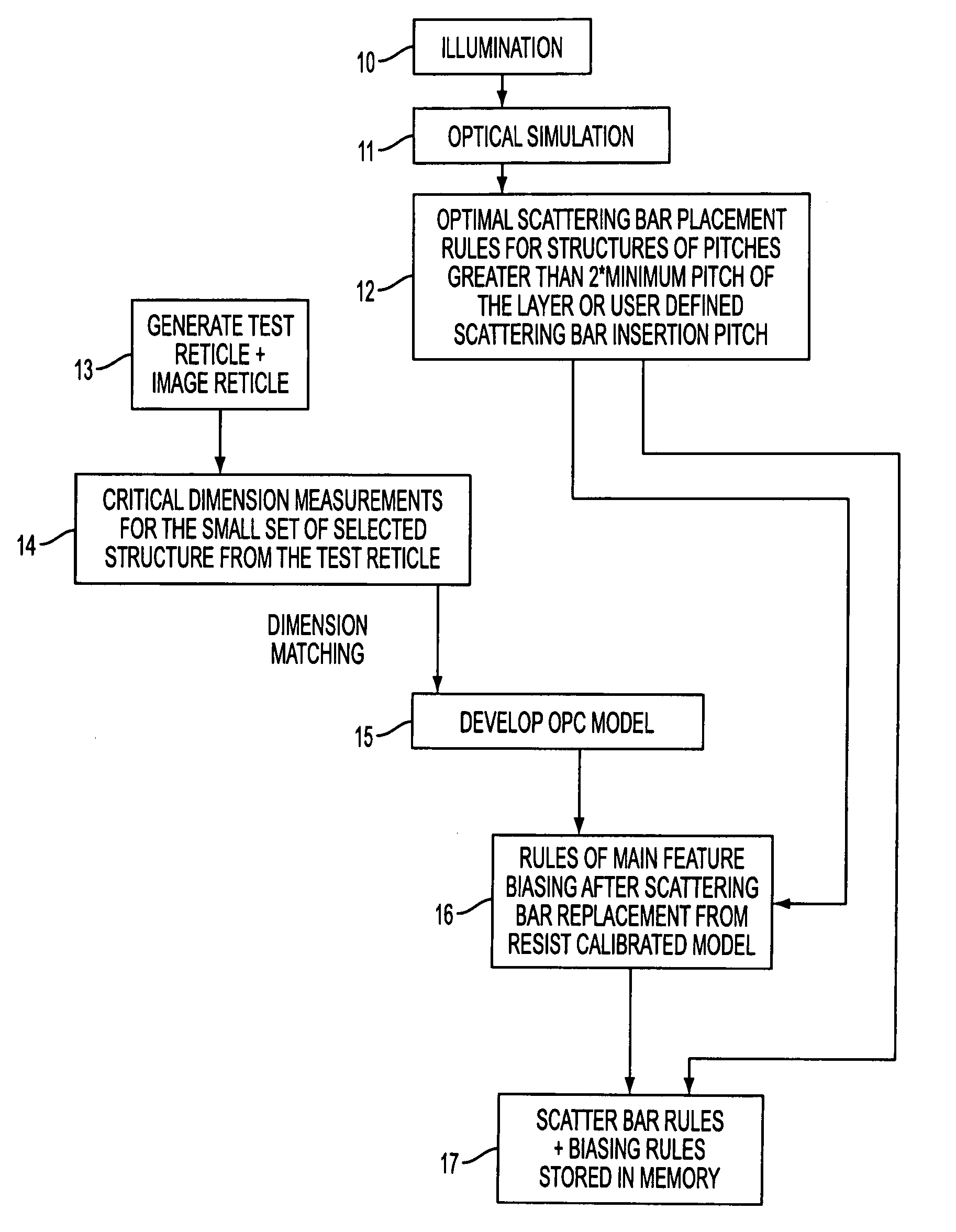
[0036]In accordance with the present invention, a method is disclosed for generating a set of rules (referred to as the OPC rule set) for automatically defining how a mask design should be modified to include OPC techniques for improving printing performance. Such OPC techniques, include, but are not limited to scatter bar assist features, feature biasing and serif placement. As explained below, once the OPC rule set has been generated for a given illumination setting, any reticle design can be automatically modified to include OPC techniques based on the OPC rule set. As such, there is no need to perform a trial and error placement for each mask design in order to modify the mask to include OPC techniques. However, a new OPC rule set needs to be generated each time the illumination setting or the resist process is changed.

[0037]FIG. 1 is a flow chart illustrating an exemplary embodiment of the method for generating the OPC rule set in accordance with the present invention. As an ov...


PUM


Abstract

A method of automatically applying optical proximity correction techniques to a reticle design containing a plurality of features. The method comprises the steps of: (1) generating a first set of rules for applying scatter bar assist features to the plurality of features for a given illumination setting; (2) generating a second set of rules for applying biasing to the plurality of features for said given illumination setting; (3) forming a look-up table containing the first set of rules and the second set of rules; and (4) analyzing each of the plurality of features with the first set of rules and the second set of rules contained in the look-up table to determine if either the first set of rules or the second set of rules is applicable to a given feature. If either the first set of rules or the second set of rules is applicable to the given feature, the given feature is modified in accordance with the applicable rule.

Description

FIELD OF THE INVENTION[0001]The present invention generally relates to photolithography, and in particular to a method of generating a set of rules for automatically applying optical proximity correction techniques to a mask pattern to be imaged on a substrate.[0002]The present invention also relates to the use of such a calibration technique in a lithographic projection apparatus, which generally comprises:[0003]a radiation system for supplying a projection beam of radiation;[0004]a support structure for supporting patterning means (e.g., mask), the patterning means serving to pattern the projection beam according to a desired pattern;[0005]a substrate table for holding a substrate; and[0006]a projection system for projecting the patterned beam onto a target portion of the substrate.BACKGROUND OF THE INVENTION[0007]Lithographic apparatus can be used, for example, in the manufacture of integrated circuits (ICs). In such a case, the mask may contain a circuit pattern corresponding to...

Claims


Application Information

Patent Timeline
IPC IPC(8): G06F17/50G03F1/00G03F1/36G03F7/20H01L21/027
CPCG03F1/144G03F7/70441G03F1/36H01L21/027
Inventor SHI, XUELONGCHEN, JANG FUNG
Owner ASML NETHERLANDS BV
Why Eureka
Try Eureka