
Method and apparatus for splitting of specimens into multiple channels of a microfluidic device

a microfluidic device and specimen technology, applied in the field of microfluidics, can solve the problems of incompatibility of reagents with each other, difficult preparation of such devices, and inability to achieve desired reaction

Inactive Publication Date: 2006-10-24
SIEMENS HEALTHCARE DIAGNOSTICS INC
View PDF213 Cites 81 Cited by
  • Summary
  • Abstract
  • Description
  • Claims
  • Application Information

AI Technical Summary

Benefits of technology

[0013]By using multiple reagent wells connected by capillary passageways, sample fluids can be provided with many separate treatments in a predetermined sequence, thereby avoiding many of the problems which are difficult to overcome with conventional test strips. In a preferred embodiment, one sample well supplies a series of metering wells having volumes defining the amount of the sample to be analyzed. Each metering well is in fluid communication with one or more reagent wells and associated conditioning wells via capillary passageways containing capillary stops for preventing transfer of the sample liquid until overcome by application of an opposing force e.g., centrifugal force. The samples may be further divided by additional metering wells and thereafter further reacted in additional reagent wells and their associated conditioning wells.

Problems solved by technology

Preparation of such devices is difficult when the sample has a complex composition, as many bodily fluids do.
Other components in the sample fluid may interfere with the desired reaction and they must be separated from the sample or their effect neutralized.
Sometimes, the reagents are incompatible with each other.
These and other problems make it difficult to provide in a single device the reagents and other components which are needed for a particular assay.
However, it is typical of biological assays that the samples are small and therefore it follows that the processing steps must be carried out in very small equipment.
Scaling down laboratory equipment to the size needed for samples of about 0.02 to 50 μL is not feasible and a different approach is used.

Method used


Image

  • Method and apparatus for splitting of specimens into multiple channels of a microfluidic device
  • Method and apparatus for splitting of specimens into multiple channels of a microfluidic device
  • Method and apparatus for splitting of specimens into multiple channels of a microfluidic device

Examples


example 1

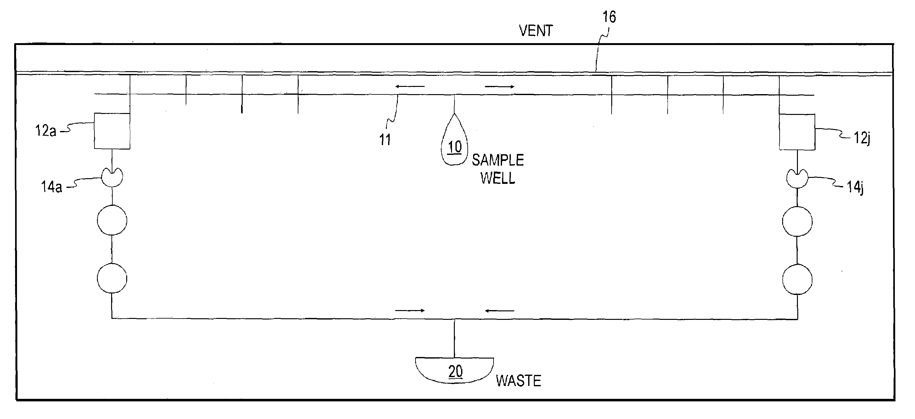
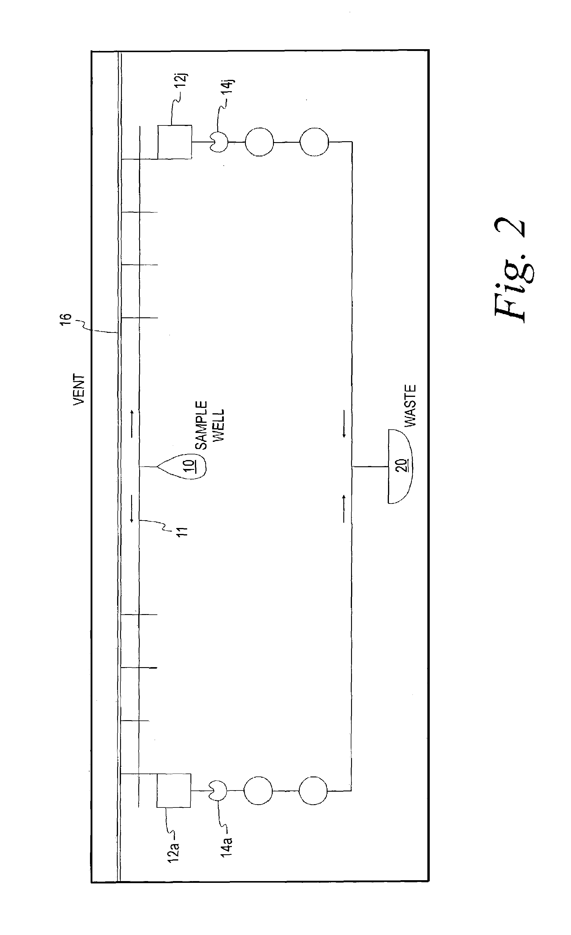
[0071]A multiple channel device was made in a plastic chip having an annular shape using diamond bit drills and lasers. Six reaction channels were arrayed on each side of a central inlet well in an arrangement similar to that of FIG. 2. The inlet well had a volume of 37 μL, each metering well and reaction well had a volume of 1 μL, and the waste well held 37 μL. The capillary passageways were 30 μm wide and 30 μm deep. All of the wells and capillary channels were made by hydrophilic by plasma activation or polymerization. Each of the wells was vented to allow air to escape as liquid fills the space. A hydrophilic capillary stop was added at the outlet of the metering well and the reaction wells to prevent flow through the connecting capillary passageways until sufficient centrifugal force is applied. A 20 μL sample of urine was placed in the inlet well from which it wicked into the capillaries 11 and then into the individual metering or reaction wells 12a–j by capillary forces. The ...

example 2

[0072]FIG. 12 illustrates an alternative configuration similar to FIG. 2 except that each of the metering wells 12a–f are used to supply a portion of their sample to each of five reaction wells e.g. 13a to 13f. From each of these reaction wells is metered five additional portions 14a–f (1–5) to each of five more reaction wells 15a–f (1–5). In one application, 12a meters 2 μL of the specimen into the 13a reaction area, which contains 10 μL of lysis buffer. A lithum salt in the lysis buffer, as described in U.S. Pat. No. 5,258,311 causes the red blood cells to lysis and allows antibodies to react with the glycated peptides of hemoglobin. Five additional aliquotes of 0.3 μL are metered by 14a (1–5) into separate reaction areas 15a (1–5) for detection of HbAlc by measurement of agglutination of immuno reagents, as described U.S. Pat. No. 5,372,918.


PUM

PropertyMeasurementUnit
depthaaaaaaaaaa
widthaaaaaaaaaa
volumeaaaaaaaaaa

Abstract

A microliter liquid sample, particularly a biological sample, is analyzed in a device employing centrifugal and capillary forces. The sample is moved by capillary forces into one or more metering wells which define the amount of the sample to be analyzed in subsequent steps. The defined amount of the sample is transferred from the metering wells to one or more conditioning and reagent wells for measuring the amount of an analyte contained in each metered amount of the sample.

Description

BACKGROUND OF THE INVENTION[0001]This invention relates generally to the field of microfluidics, as applied to analysis of various biological and chemical compositions. More particularly, the invention provides methods and apparatus for carrying out analyses, using both imposed centrifugal forces and capillary forces resulting from the surface properties of the passageways in the apparatus[0002]To determine the presence (or absence) of, or the amount of an analyte, such as glucose, albumin, or bacteria in bodily or other fluids, a reagent device is generally used to assist a technician performing the analysis. Such reagent devices contain one or more reagent areas at which the technician can apply the sample fluid and then compare the result to a standard. For example, a reagent strip is dipped into the sample fluid and the strip changes color, the intensity or type of color being compared with a standard reference color chart.[0003]Preparation of such devices is difficult when the ...

Claims


Application Information

Patent Timeline
Patent Type & Authority Patents(United States)
IPC IPC(8): C12M1/34C12M3/00B01L3/00G01N
CPCB01L3/5027B01L3/5025B01L3/50273B01L2200/0605B01L2200/0684B01L2300/0816B01L2300/0864B01L2300/0867B01L2300/087B01L2400/0406B01L2400/0409B01L2400/0688B01L2300/0803G01N35/00069G01N2035/00158G01N2035/00237G01N2035/1034
Inventor PUGIA, MICHAEL J.PROFITT, JAMES A.BLANKENSTEIN, GERTPETERS, RALF-PETER
Owner SIEMENS HEALTHCARE DIAGNOSTICS INC
Features
  • Generate Ideas
  • Intellectual Property
  • Life Sciences
  • Materials
  • Tech Scout
  • Unparalleled Data Quality
  • Higher Quality Content
  • 60% Fewer Hallucinations
Learn More