Surface contamination detection method and apparatus

a contamination detection and surface technology, applied in the direction of optical radiation measurement, instruments, x/gamma/cosmic radiation measurement, etc., can solve the problems of no water film hazardous to humans, and water film will break around the contaminated area, so as to improve the contaminated area that is thinly wet or dry, and the inspection speed is fast.

Active Publication Date: 2006-10-24
TEXTRON INNOVATIONS
View PDF11 Cites 10 Cited by
  • Summary
  • Abstract
  • Description
  • Claims
  • Application Information

AI Technical Summary

Benefits of technology

[0007]Infrared cameras are used to inspect the wetted surface of large parts or skins. The camera resolution and infrared emissivity properties permits the inspection of large contoured metal skins rapidly and without contact for online process monitoring. Digital images are amenable to automated defect recognition in image analysis for a highly reliable and automated inspection system with infrared cameras.
[0008]In the choice of infrared (IR) cameras, they include a near IR range between 0.9 and 1.7 μm wavelength, a mid range of 1.7-to 7 μm, and a long range between 7 and 14 μm. One skilled in the art would normally think that a near range IR infrared range camera would be most suitable for detecting organic contaminants since there is an absorption notch around 0.3 μm which provides the optimum separation between bare metal and a fluid covered surface, however, due to the low emmisivity of bare metal surfaces, a long IR range of 7–14 μm has been found to be more appropriate being less sensitive to background lighting and surface reflections. In the prior art, they have utilized infrared spectroscopy for inspecting very small samples such as wafers and chips, which involve a very costly and intrusive instrumentation techniques. The long IR range cameras can be used continuously for long periods of time without shortened life since they don't require cooling which near IR cameras require. Other work has involved laser-based FTIR spectroscopy, but are also limited to only organic contaminates, small areas and slow speed. Due to the diffuse properties of water, the angle of incidence is not particularly sensitive in infrared wavelengths (±80 degrees), therefore; the positioning of the camera is not critical. Furthermore, parts with complex shapes can be inspected easily from a single point of view.
[0010]Removal of surface contamination on aircraft parts and skins is critical for not only bonding the parts together, but also preventing corrosion. An inadequate bond of the primary adhesive caused by surface contamination can cause structural failure in the bonded joint. Also, organic contamination can prevent deoxidizing the surface of the part completely as well as the anodizing process thus weakening the bonded joint.
[0011]While the inspection process is used specifically on metal parts, it could also be used on ceramic or polymer parts as well that have comparable surface tensions. The principal object of the present invention to provide an automated surface contamination detecting method to more effectively detect surface contamination without visual inspection.
[0013]An automated inspection system is highly desirable over the current manual visual inspection with the water break test due to the hazardous conditions present around chemical processing where inspections must be performed. Focal plane array infrared cameras are used to inspect the wetted surface of large parts or skins due to the camera's resolution and infrared emissivity properties, it is quite practical to inspect a large metal skin rapidly. The contaminated areas that are thinly wetted or dry are greatly enhanced compared to the visible light inspection due to the large change in emissivity between water film and the dry metal surface. Digital images are amenable to automated defect recognition and image analysis for a highly reliable and automated inspection system with these infrared cameras.

Problems solved by technology

The water break test involves spraying or dipping a part or panel in a water rinse following a cleaning operation wherein the water forms a continuous film over the clean portion of the panel, however, due to the reduced surface tension between the water and oil or grease, the water film will break around the contaminated areas and leave no water film.
This water break test has been used for years in wet chemical processes in aerospace and other industries; however, it requires a visual inspection of the panels and parts during the deoxidizing and alkaline cleaning steps, which is quite hazardous to humans due to the use of various caustic and acid chemical processes.
In the prior art, they have utilized infrared spectroscopy for inspecting very small samples such as wafers and chips, which involve a very costly and intrusive instrumentation techniques.
Other work has involved laser-based FTIR spectroscopy, but are also limited to only organic contaminates, small areas and slow speed.

Method used


Image

  • Surface contamination detection method and apparatus
  • Surface contamination detection method and apparatus
  • Surface contamination detection method and apparatus

Examples


Embodiment Construction

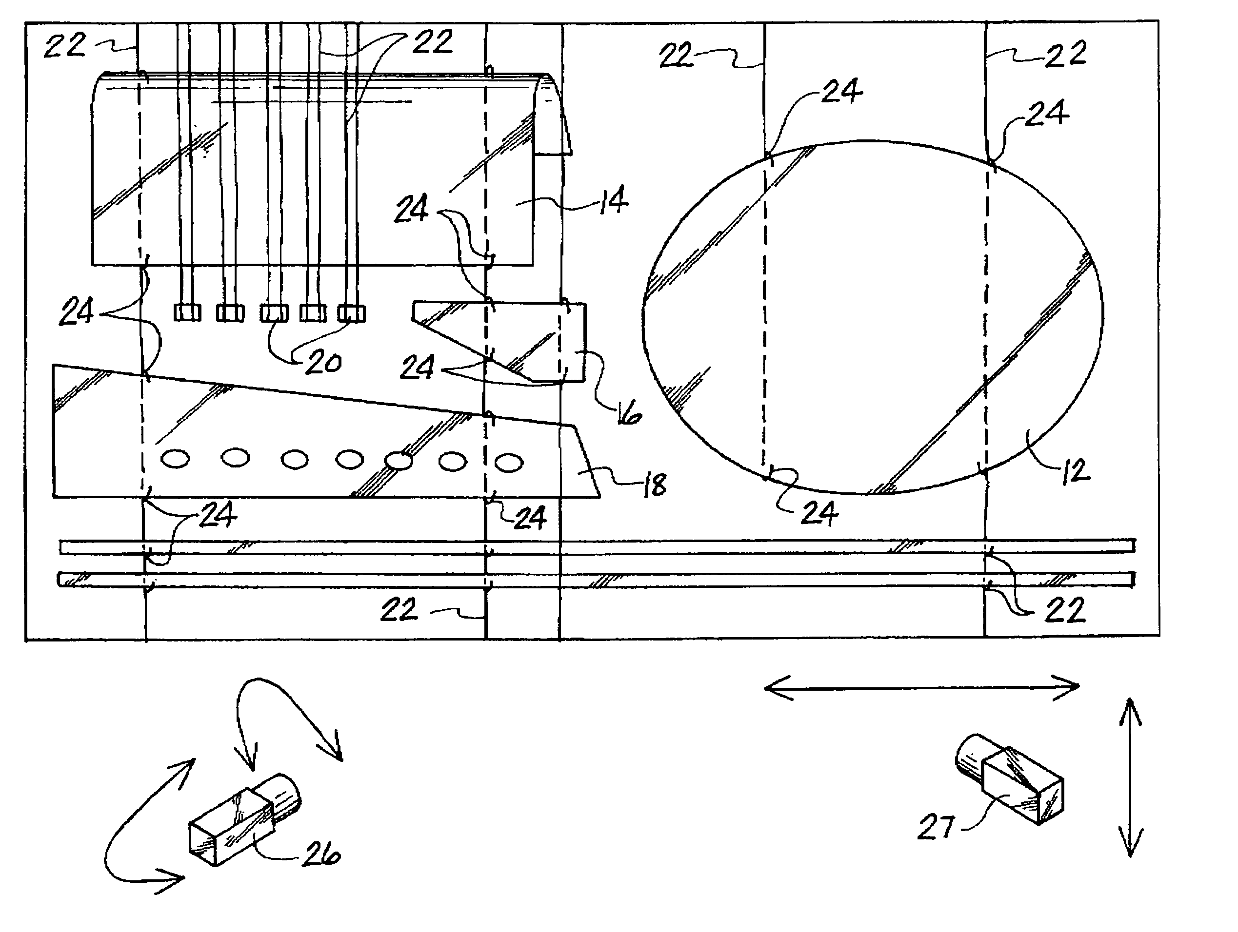
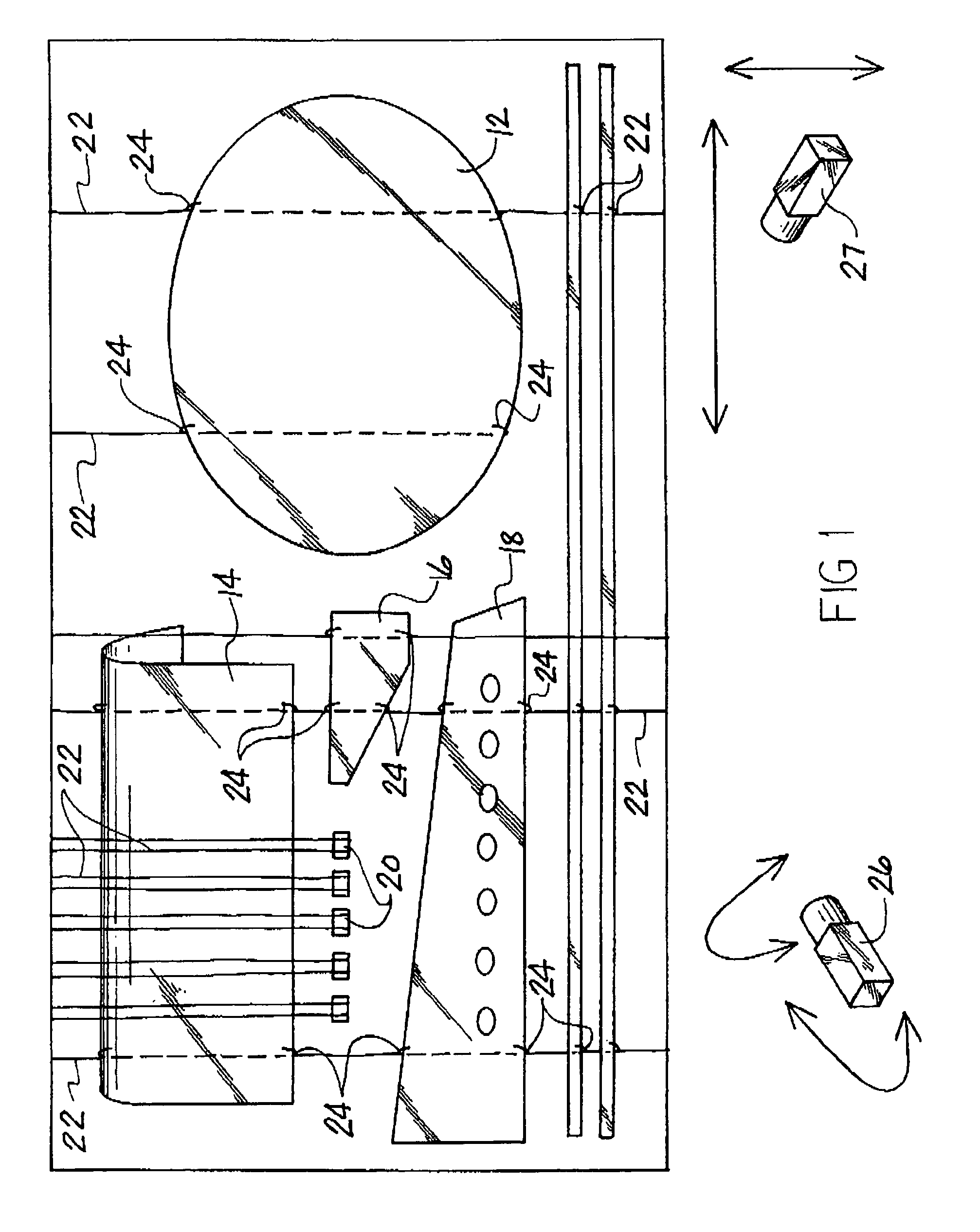
[0017]FIG. 1 is a symbolic representation of the supporting frame 10 which is supporting a variety of aircraft skins and parts 12, 14, 16, 18, and 20. The various parts are suspended within frame 10 by a series of wires 22 which are typically twisted around the part to support same, such as portions 24 which engage the part. Various curved shaped parts, such as part 14, can be examined by the present inspection process by infrared cameras 26 and 27 which have sufficiently focal distance to examine a relatively large area without movement. Cameras 26 and 27 can be fixed mounted on a pan / tilt head so as to scan the entire length of frame 10 which can be dimensioned over 30 feet in length. One of the cameras 26 or 27 can be positioned on the opposite side of support frame 10 so as to examine both sides of the part simultaneously. Frame 10 can be made of tubular steel as well as other materials, which could be impervious to various alkaline and acid dip tanks. The frames 10 are lifted a...


PUM


Abstract

A method and an apparatus for inspecting parts for surface contamination including the steps of covering the part with a film of water, and then scanning the wetted part with a infrared camera to preserve the reflected image of the reflected infrared light thereby defining a water break area of contamination.

Description

FIELD OF THE INVENTION[0001]The present invention relates to method and apparatus for inspecting for surface contamination on dense material part surfaces prior to secondary operations such as bonding, painting, anodizing or plating.BACKGROUND OF THE INVENTION[0002]There are a variety of applications for inspecting the surface cleanliness of manufactured products. A variety of systems have been developed to inspect a multiplicity of surfaces for irregular surfaces as well as contaminants on the surface such as painted panels in the automotive and appliance fields. Some of these surface inspection processes are looking for flaws in the surface or surface finish and also contamination on the surface such as oils or other organic residue. U.S. Pat. No. 4,920,385 is a flaw inspection system that used on sheet materials including aircraft panels for determining surface defects in the panel by reflecting an image of visible light off the irregular surface and thus creating a wavy image in...

Claims


Application Information

Patent Timeline
Patent Type & Authority Patents(United States)
IPC IPC(8): G01T1/169
CPCG01N21/88G01N21/94G01N21/3563G01N21/35
Inventor AMOS, JAY M.GILBERT, ALAN R.
Owner TEXTRON INNOVATIONS
Why Eureka
Try Eureka