RF-mems switch

a micro-electromechanical system and switch technology, applied in waveguide devices, relays, contacts, etc., can solve the problems of insufficient improvement of insufficient reduction of etc., to achieve the effect of improving the isolation characteristics of the switch and reducing the insertion loss and return loss of the switch

Active Publication Date: 2006-10-24
MURATA MFG CO LTD
View PDF12 Cites 22 Cited by
  • Summary
  • Abstract
  • Description
  • Claims
  • Application Information

AI Technical Summary

Benefits of technology

[0008]To overcome the problems described above, preferred embodiments of the present invention provide an RF-MEMS switch which su...

Problems solved by technology

However, since known RF-MEMS switches include one switching device which is provided with only one movable electrode, there is a possibility that ...

Method used


Image

  • RF-mems switch
  • RF-mems switch
  • RF-mems switch

Examples


Embodiment Construction

[0036]Preferred embodiments of the present invention will now be described with reference to the drawings.

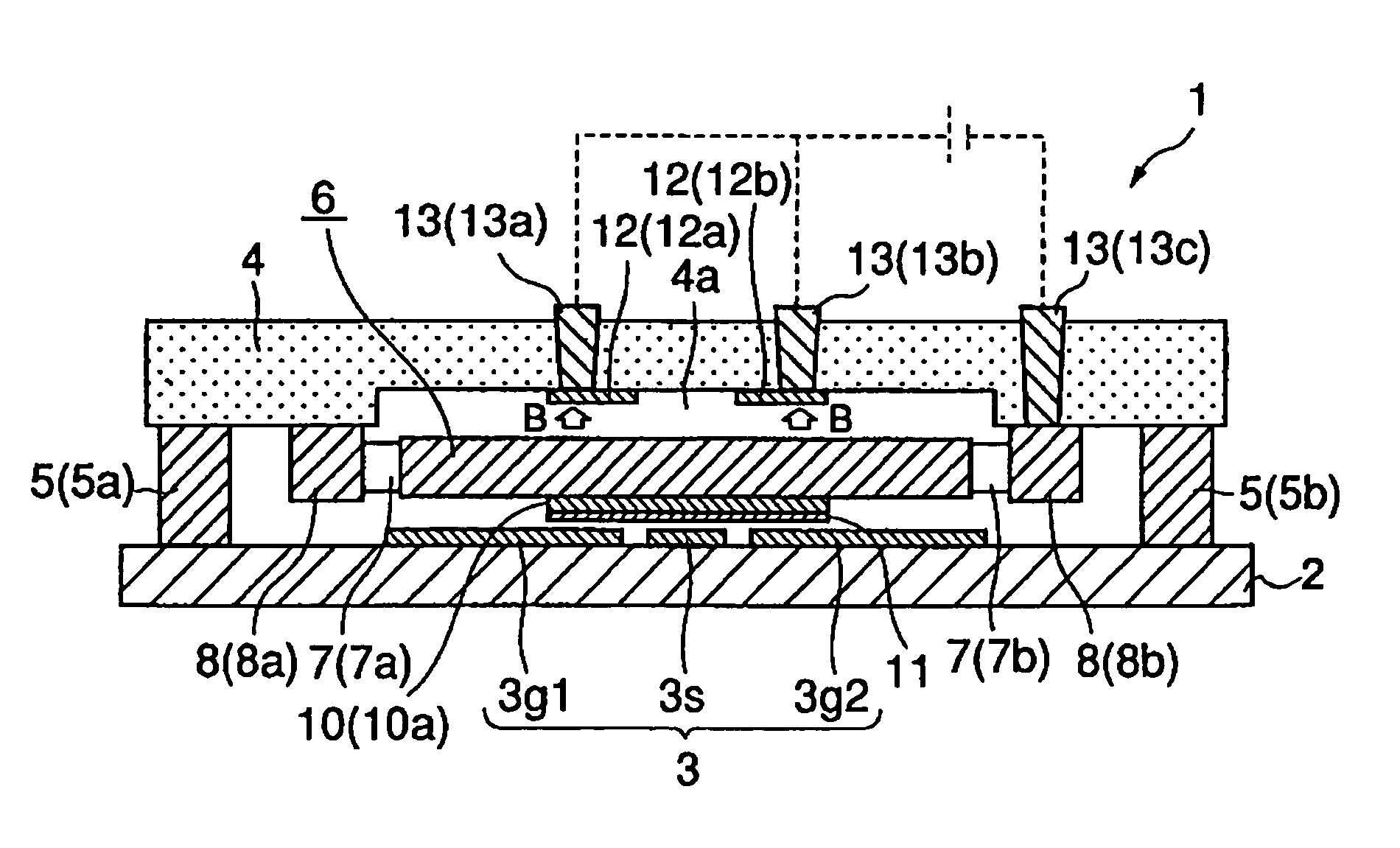
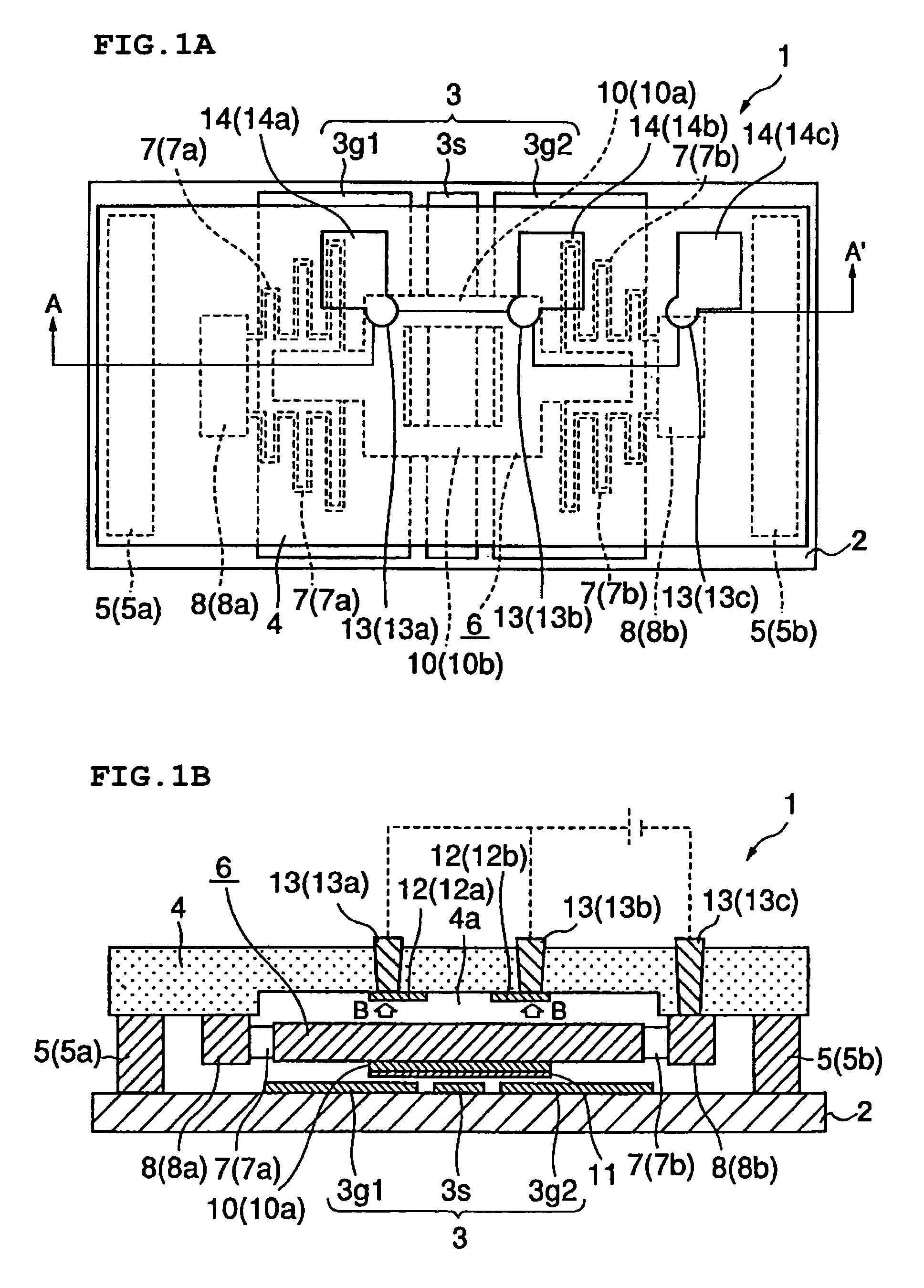
[0037]FIG. 1A is a schematic plan view showing an RF-MEMS switch 1 according to a first preferred embodiment of the present invention. FIG. 1B is a schematic cross-sectional view taken along the line A–A′ in FIG. 1A.

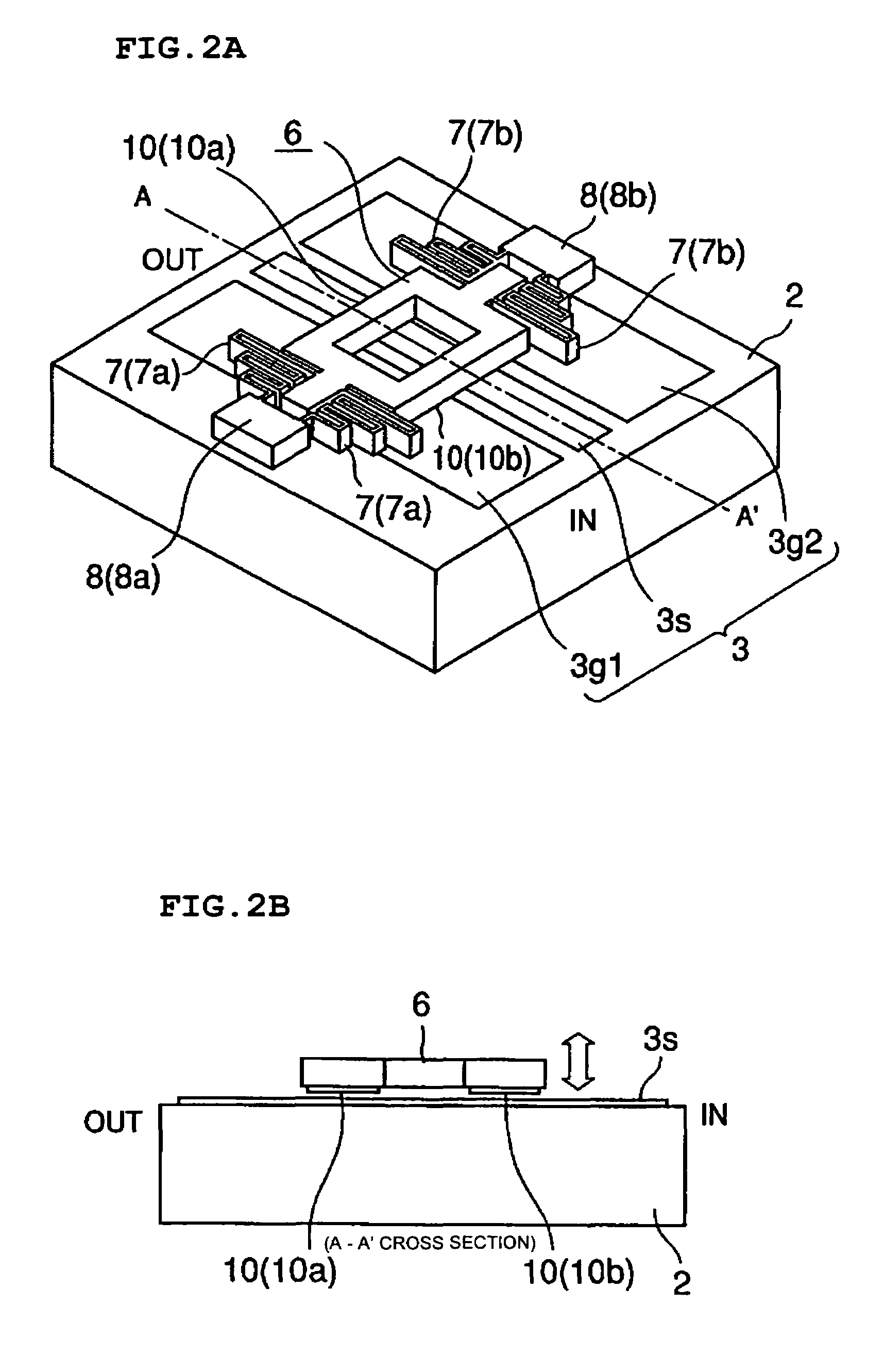
[0038]The RF-MEMS switch 1 according to the first preferred embodiment is assembled in an RF circuit and defines a switching device for a coplanar line. The RF-MEMS switch 1 preferably includes a substrate 2 (for example, a silicon substrate or a sapphire substrate), and a coplanar line (coplanar waveguide (CPW) line) 3, which defines an RF signal-conducting unit, is arranged on the substrate 2. The coplanar line 3 is a line for transmitting an RF signal and includes a signal line 3s and two ground lines 3g1 and 3g2. The signal line 3s is arranged between the ground lines 3g1 and 3g2 but is not in contact with them. The signal line 3s and the ground lines 3g1 and 3g2...


PUM


Abstract

An RF-MEMS switch includes a plurality of movable electrodes disposed with a space provided therebetween in the direction of RF signal conduction of an RF signal-conducting unit which is provided above the RF signal-conducting unit. A movable electrode displacing unit for displacing all the movable electrodes at the same time in the same direction towards or away from the RF signal-conducting unit is provided. The electrical length of the RF signal-conducting unit sandwiched between the movable electrodes is set such that the amplitude of a combined signal including signals reflected in positions of the RF signal-conducting unit facing the movable electrodes is less than the amplitude of each of reflected signals reflected in positions of the RE signal-conducting unit facing the movable electrodes when the movable electrodes are displaced away from the RF signal-conducting unit and signal conduction of the RF signal-conducting unit is switched on.

Description

BACKGROUND OF THE INVENTION[0001]1. Field of the Invention[0002]The present invention relates to RF microelectromechanical systems (RF-MEMS) switches assembled in RF circuit modules for surveillance radar scanners or other devices.[0003]2. Description of the Related Art[0004]As an example of switching devices for RF signals, such as millimeter-wave and microwave signals, a shunt RF-MEMS switch (shunt switching device) is disclosed, for example, in Non-patent Document 1, entitled “High-Isolation CPW MEMS Shunt Switches-Part1: Modeling,” (IEEE Transactions on Microwave Theory Techniques, Vol. 48. No. 6, June 2000, pp. 1045–1052) written by J. B. Muldavin, Student Member, IEEE et al.[0005]This type of RF-MEMS switch includes an RF signal-conducting unit provided on a substrate thereof. Also, an electrode facing at least a portion of the RF signal-conducting unit is disposed above the substrate. In such an RF-MEMS switch, displacing the electrode towards or away from the substrate using...

Claims


Application Information

Patent Timeline
IPC IPC(8): H01H51/22H01H59/00H01P1/12
CPCH01H59/0009H01P1/127H01G5/16H01G5/40H01H2001/0078H01H2001/0084H01H59/00
Inventor KAWAI, HIROSHI
Owner MURATA MFG CO LTD
Why Eureka
Try Eureka