Spin valve magnetoresistive element having pinned magnetic layer composed of epitaxial laminated film having magnetic sublayers and nanomagnetic interlayer

a magnetic layer and spin valve technology, applied in the field of spin valve magnetoresistive elements having pinned magnetic layer, can solve the problems of preventing improvement of the output of the magnetic sensor, structure cannot appropriately pin the magnetization direction of the pinned ferromagnetic layer, and cannot solve the problem of reducing the magnetic field of the pinned layer,

Inactive Publication Date: 2006-10-24
TDK CORPARATION
View PDF10 Cites 23 Cited by
  • Summary
  • Abstract
  • Description
  • Claims
  • Application Information

AI Technical Summary

Benefits of technology

[0050]Furthermore, the first magnetic sublayer of the pinned magnetic layer is composed of CoxFey (y≧20, x+y=100) in the vicinity of the boundary adjacent to the nonmagnetic interlayer because the Ruderman-Kittel-Kasuya-Yoshida (RKKY) interaction between the first magnetic sublayer and other magnetic sublayer via the nonmagnetic interlayer can be increased.
[0051]The iron content in the first magnetic sublayer of the pinned magnetic layer may gradually increase from the boundary adjacent to the nonmagnetic metal layer to the boundary adjacent to the nonmagnetic interlayer.

Problems solved by technology

However, the shunt loss of the sense current prevents improvement of the output of the magnetic sensor.
Unfortunately, this structure cannot appropriately pin the magnetization direction of the pinned ferromagnetic layer 70.
However, Japanese Unexamined Patent Application Publication No. 2000-113418 does not consider or discuss optimization of the magnetostriction of the pinned magnetic layer let alone disclose a specific construction to optimize the magnetostriction of the pinned magnetic layer.

Method used


Image

  • Spin valve magnetoresistive element having pinned magnetic layer composed of epitaxial laminated film having magnetic sublayers and nanomagnetic interlayer
  • Spin valve magnetoresistive element having pinned magnetic layer composed of epitaxial laminated film having magnetic sublayers and nanomagnetic interlayer
  • Spin valve magnetoresistive element having pinned magnetic layer composed of epitaxial laminated film having magnetic sublayers and nanomagnetic interlayer

Examples


examples

[0186]The following multilayer films were formed and were annealed at 290° C. for four hours. Then the magnetostriction of each film was measured.

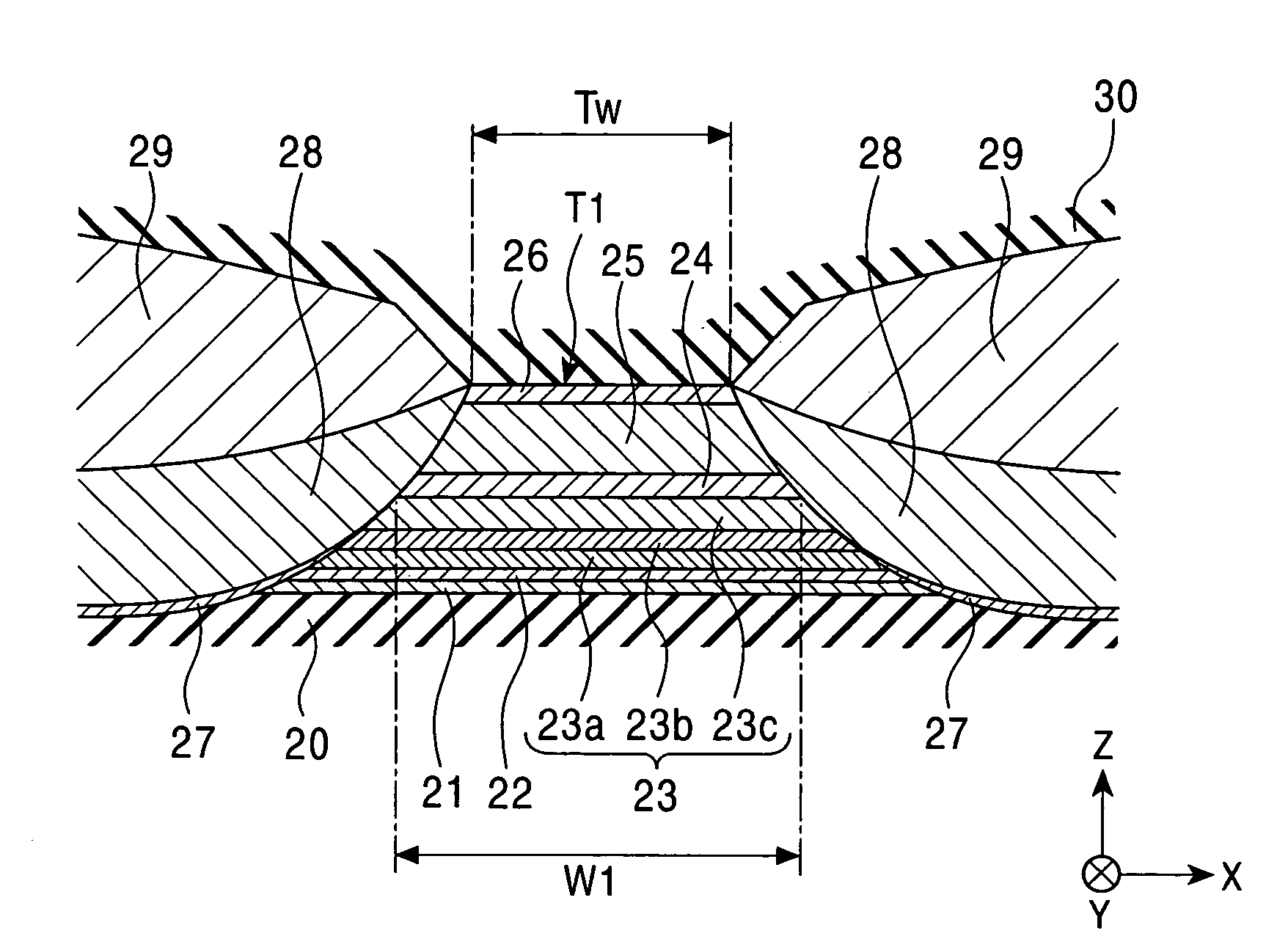
[0187]One multilayer film included a silicon substrate / alumina (1,000 Å) / (Ni0.8Fe0.2)60Cr40 (52 Å) / nonmagnetic metal layer (underlayer) / pin 1 layer / Ru (9 Å) / pin 2 (40 Å) / Cu (85 Å) / Ta (30 Å).

[0188]According to this multilayer film, for example, the second magnetic sublayer, the nonmagnetic conductive layer, and the free magnetic layer are not formed, thereby permitting accurate measurement of the magnetostriction of the first magnetic sublayer 23a. The nonmagnetic metal layer (i.e., underlayer) is composed of Ru or Pt50Mn50 (atomic percent); a pin 1 layer is composed of Co, Co90Fe10 (atomic percent), or Fe50Co50 (atomic percent); and a pin 2 layer is composed of Co or Co90Fe10 (atomic percent). Hereinafter, the Co90Fe10 (atomic percent) is referred to as “CoFe” and the Fe50Co50 (atomic percent) is referred to as “FeCo”.

[0189]The magnetostri...


PUM

PropertyMeasurementUnit
widthaaaaaaaaaa
distanceaaaaaaaaaa
distanceaaaaaaaaaa

Abstract

A magnetic sensor includes a pinned magnetic layer having first and second magnetic sublayers sandwiching a nonmagnetic metal layer. The nonmagnetic metal layer contains at least one of Ru, Re, Os, Ti, Rh, Ir, Pd, Pt, and Al. The atoms in the first magnetic sublayer and the atoms in the nonmagnetic metal layer overlap with each other, while each of the crystal structures is deformed. The deformations in the crystal structure of the first magnetic sublayer increase the magnetostriction constant, thereby increasing the magnetoelastic effect of the magnetic sensor.

Description

[0001]This application claims the benefit of priority to Japanese Patent Application No. 2003-048688, herein incorporated by reference in its entirety.BACKGROUND OF THE INVENTION[0002]1. Field of the Invention[0003]The present invention relates to a magnetic sensor having a free magnetic layer, a nonmagnetic conductive layer, and a pinned magnetic layer, and in particular, to a magnetic sensor that pins the magnetization of the pinned magnetic layer by means of a uniaxial anisotropy of the pinned magnetic layer itself.[0004]2. Description of the Related Art[0005]Recently, most magnetic heads mounted in magnetic recording and playback devices include a spin valve magnetic sensor that uses the giant magnetoresistive (GMR) effect.[0006]The spin valve magnetic sensor includes a ferromagnetic film called a pinned magnetic layer, a ferromagnetic soft magnetic film called a free magnetic layer, and a nonmagnetic film called a nonmagnetic conductive layer. The nonmagnetic conductive layer i...

Claims


Application Information

Patent Timeline
Patent Type & Authority Patents(United States)
IPC IPC(8): G11B5/39G01R33/09H01F10/16H01F10/30H01F10/32H01F41/30H01L43/08
CPCB82Y25/00B82Y40/00G01R33/093G11B5/3912H01F10/3272H01F41/302G11B5/3932Y10T29/49034H01F10/30
Inventor HASEGAWA, NAOYAUMETSU, EIJISAITO, MASAMICHIIDE, YOSUKE
Owner TDK CORPARATION
Why Eureka
Try Eureka