
Variable displacement pump

a variable capacity, pump technology, applied in the direction of machines/engines, liquid fuel engines, positive displacement liquid engines, etc., can solve the problems of unstable movement of the cam ring and difficulty in enhancing the response for increasing the discharge amount of the pump

Inactive Publication Date: 2006-10-31
TOYODA MASCH WORKS LTD
View PDF9 Cites 18 Cited by
  • Summary
  • Abstract
  • Description
  • Claims
  • Application Information

AI Technical Summary

Benefits of technology

[0008]As in the hydraulic pump, the internal pressure chamber and the load pressure chamber are formed at the opposite ends of the differential pressure control valve loaded by the thrust force of the spring toward the internal pressure chamber to be applied with the internal pressure and the load pressure from the front side and the back side of the orifice respectively, the eccentric amount of the cam ring is maximized when a difference of the internal pressure and the load pressure is small during rotation of the pump at a low speed. Thus, the discharge amount of the pump is rapidly increased in proportion to the rotation speed of the pump. When the differential pressure control valve is moved by an increase of the difference in pressure, the eccentric amount of the cam ring is reduced by a difference in pressure between the action chambers. As a result, the discharge amount of hydraulic fluid does not increase even if the rotation speed of the pump is increased. The thrust force of the spring acting on the differential pressure control valve is increase or decreased in accordance with an increase or a decrease of the load pressure applied from the back side of the orifice, and the difference in pressure acting on the differential pressure control valve against the thrust force of the spring is also increased or decreased in accordance with the increase or the decrease of the load pressure. Accordingly, when the eccentric amount of the cam ring is reduced by the difference in pressure between the action chambers, the rotation speed of the pump is increased or decreased. Thus, the limit value of the discharge amount of the pump is increased or decreased.

Problems solved by technology

This causes the movement of the cam ring unstable.
In addition, it is difficult to enhance the response for increase of the discharge amount of the pump relative to an increase of the load pressure.

Method used


Image

  • Variable displacement pump
  • Variable displacement pump
  • Variable displacement pump

Examples


first embodiment

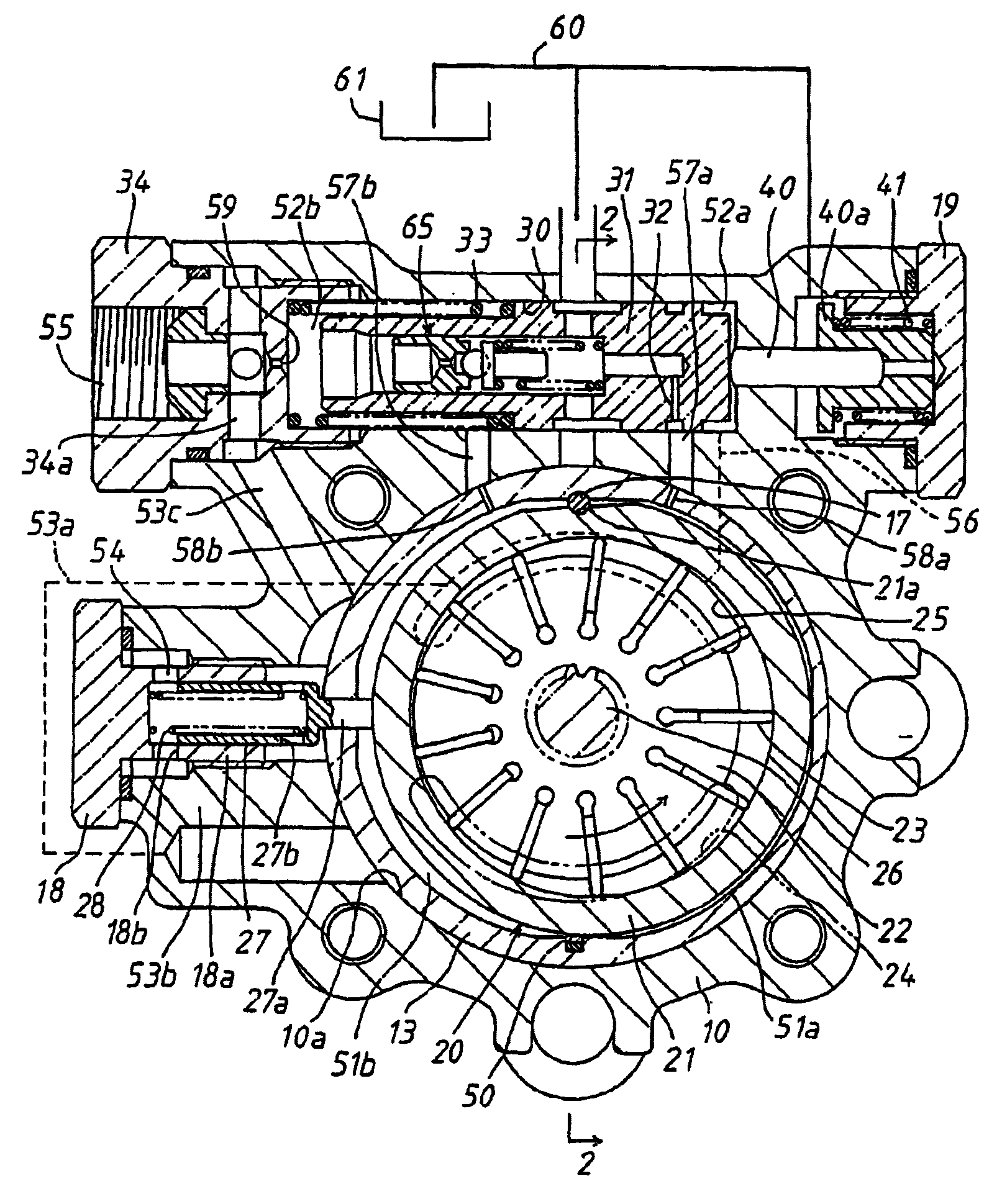
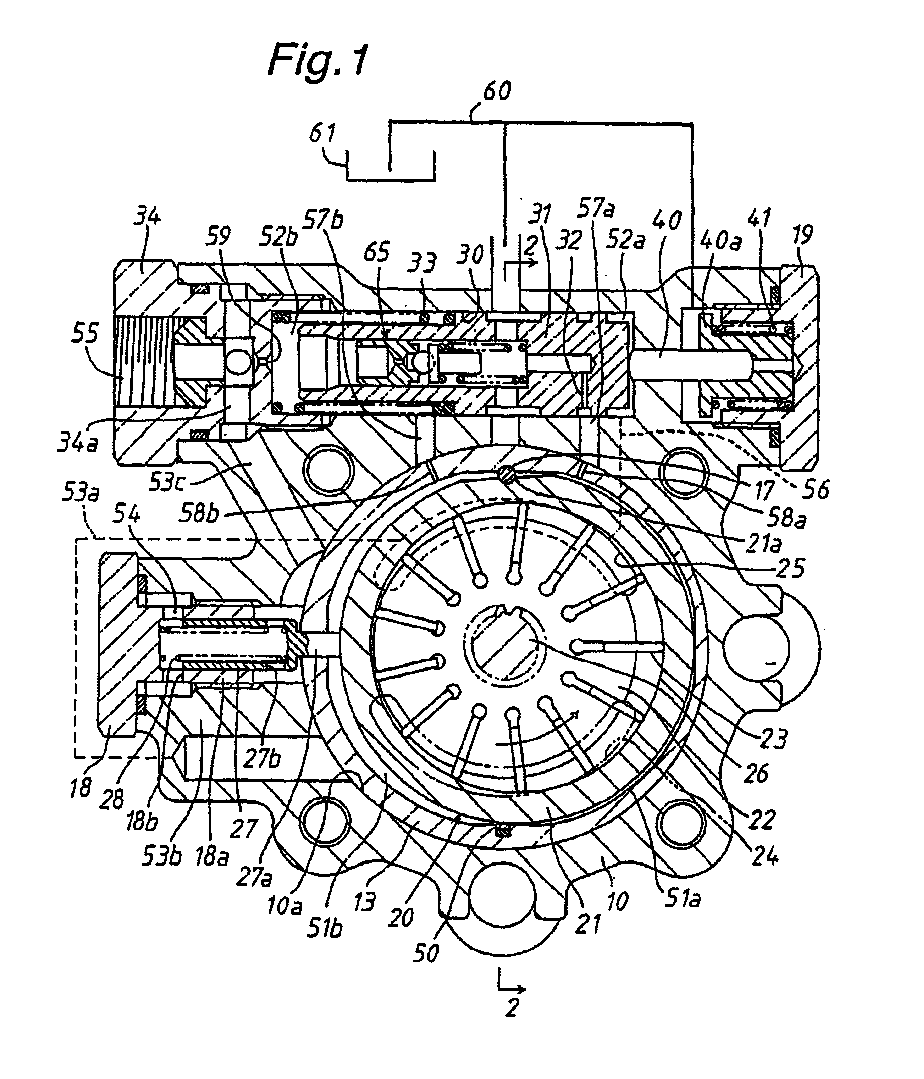
[0019]Hereinafter, a hydraulic pump in accordance with the present invention will be described with reference to FIGS. 1–4. The hydraulic pump of the variable capacity type is used as a supply source of hydraulic fluid for a power-assisted steering apparatus, the main components of which are composed of a housing 10 covered with an end wall member 11 in a liquid-tight manner, a pump shaft 26 mounted within the housing 10, a rotor 22 mounted on the pump shaft 26 for rotation therewith, a vane pump assembly 20 having a cam ring 21 movable in a radial direction, a differential pressure control valve 31 for controlling the movement of the cam ring 21, and a variable orifice 54 located in discharge passages 53a, 53b and 53cof the vane pump assembly 20.

[0020]As shown in FIGS. 1 and 2, the pump shaft 26 is rotatably supported at its intermediate portion and rear end on the housing 10 and end wall member 11 respectively through a bearing. An internal cylindrical surface 10a is formed in the...

second embodiment

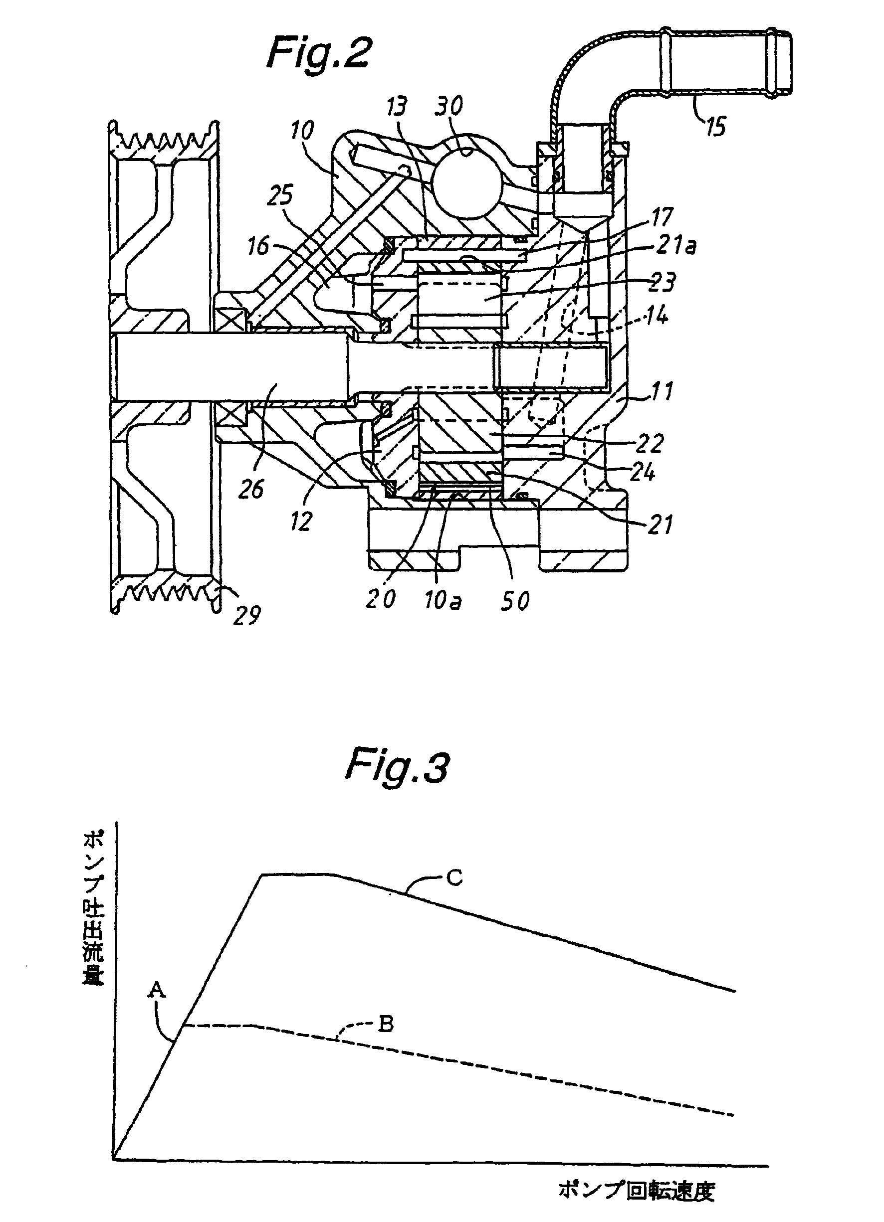
[0041]In this second embodiment, a difference in pressure between the front and back sides of variable orifice 54 is maintained in a small value in a condition where the pump is rotated at a low speed. Thus, as shown in FIG. 5, the differential pressure control valve 31 is maintained in contact with the distal end of valve bore 30 in the internal pressure chamber 52a under the load of thrust coil spring 33A so that the first action chamber 51a is communicated with the fluid reservoir 61 and that the cam ring 21 is pressed toward the first action chamber 51a under the load of thrust coil spring 28 to maximize the amount of hydraulic fluid discharged from the pump. In such a condition, the discharge amount of hydraulic fluid rapidly increases in accordance with an increase of rotation speed of the pump, as shown by the characteristic line A in FIG. 3.

[0042]When the difference in pressure between the front and back sides of variable orifice 54 increases in accordance with an increase o...

third embodiment

[0052]In this third embodiment, the difference in pressure between the front and back sides of variable orifice 54 (shown in FIG. 5) is small during rotation of the pump at a low speed. In such an instance, the differential pressure control valve 35 is pressed into contact with the distal end of internal pressure chamber 52a under the load of thrust spring 33B as shown in FIG. 8(a), and the cylindrical portion 36 is maintained in engagement with the spring receiver 37a under the load of valve spring 38. Thus, the first action chamber 51a is applied with low pressure from the fluid reservoir 61 so that the cam ring 21 is pressed toward the first action chamber 51a under the load of thrust spring 28 to maximize the discharge amount of the pump. Accordingly, the discharge amount of the pump rapidly increases in response to an increase of the rotation speed of the pump as shown the characteristic line A in FIG. 3.

[0053]When the difference in pressure between the front and back sides of ...


PUM


Abstract

In a hydraulic pump, a cam ring is provided in a cylindrical adaptor for movement in a radial direction, and a differential pressure control valve is provided to control internal pressure and load pressure at the front and back sides of a variable orifice to be introduced into action chambers and formed at the opposite sides of the cam ring for controlling a discharge amount of the pump in accordance with the rotation speed of the pump. The differential pressure control valve is operated under the internal pressure and load pressure respectively introduced into action chambers and the load of a thrust spring biasing the differential pressure control valve toward the internal pressure chamber. The load of the thrust spring is increased or decreased in accordance with an increase or a decrease of the load pressure. The increase or decrease of the load pressure is effected by a load pressure responsive piston loaded by a thrust spring and engaged with the differential pressure control valve at one end thereof in the internal pressure chamber.

Description

FIELD OF THE INVENTION[0001]The present invention relates to a hydraulic pump of the variable capacity type suitable for use in a power-assisted steering apparatus of an automotive vehicle, and more particularly to a hydraulic pump of the variable capacity type capable of controlling an amount of hydraulic fluid discharged therefrom in accordance with load pressure applied thereto.DESCRIPTION OF THE PRIOR ART[0002]Disclosed in Japanese Patent Publication No. 2(1990)-61638) is a hydraulic pump of the variable capacity type capable of controlling an amount of hydraulic fluid discharged therefrom in accordance with load pressure applied thereto. In the hydraulic pump, a cam ring is mounted within a housing body in such a manner as to be variable in its eccentric amount relative to the center of a rotor of a vane pump assembly and is loaded by a spring in an eccentric direction, a piston is provided to move the cam ring against the spring when operated by a difference in pressure betwee...

Claims


Application Information

Patent Timeline
IPC IPC(8): F03C2/00F04C2/00F04C2/344F04C14/22F04C14/24
CPCF04C14/226
Inventor SUZUKI, MIKIOINAGUMA, YOSHIHARUSUZUKI, KEIJIKATO, HIDEYAIKEDA, TSUYOSHI
Owner TOYODA MASCH WORKS LTD
Learn More