Impact layer technology shaft

Active Publication Date: 2006-10-31
SPORT MASKA
View PDF22 Cites 13 Cited by
  • Summary
  • Abstract
  • Description
  • Claims
  • Application Information

AI Technical Summary

Benefits of technology

[0007]It is a further advantage of the present invention to provide a composite hockey stick shaft having increased strength and durability along the shaft thereof.
[0008]The present invention generally provides for a composite hockey stick shaft wherein the structure of the shaft, the fibers in the resin matrix known as the constraining layer, is overlaid by an outer layer of viscoelastic material disposed thereon which acts to dampen and absorb the shocks and impacts which are administered to the shaft during play. In particular, the viscoelastic material may be disposed over substantially the whole length of the shaft, and cover all four sides of the shaft, or alternatively, it may be disposed over only part of the length of the shaft, and may cover one or more of the four sides of the shaft.
[0009]In a further embodiment, the viscoelastic layer may itself be overlaid with a base layer of composite materials whose function may be to provide protection to the viscoelastic layer against mechanical wear and tear (damage) of the viscoelastic layer. The base layer may be hardened and may be thin, i.e. thinner than the so as to minimize weight. The base layer may overlay the whole of the viscoelastic layer or only a portion thereof.
[0010]In accordance with a general aspect of the present invention, the constraining layer may be assembled and manufactured in accordance with any number of well-known methods of fabricating composite hockey stick shafts. For example, the shaft may be thin-walled, hollow or may be full or may comprise any combination of materials and constructions. The constraining layer may provide reinforcement and stiffness to the shaft structure, while acting as an anchor for the viscoelastic layer. As may be understood, in accordance with a general aspect, the constraining layer is the core of the shaft and may provide all, i.e. substantially all of the structural strength, of the shaft.
[0011]Over the constraining layer,

Problems solved by technology

However, composite hockey stick shafts may exhibit poor or sub-standard resistance to direct impacts thereon which stick shafts are often subjected to during play, in particular when compared to wood shafts.
For example, composite hockey stick shafts which receive a direct hit thereon, from either another stick, a puck, or wh

Method used


Image

  • Impact layer technology shaft
  • Impact layer technology shaft
  • Impact layer technology shaft

Examples


Embodiment Construction

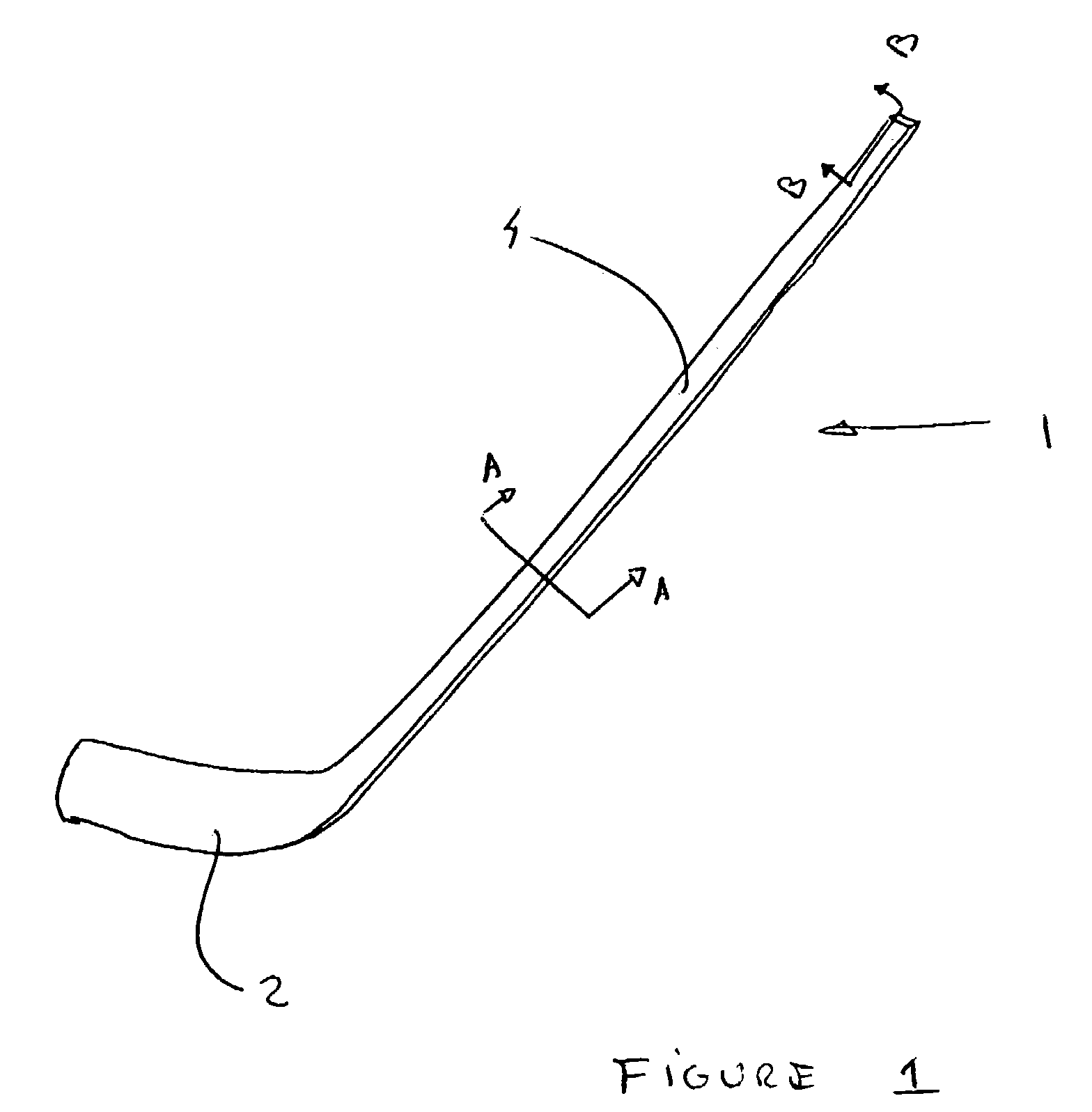
[0034]FIG. 1 is an illustration of a hockey stick 1 comprising a shaft which is attached to a blade. As may be understood, shaft 4 is made of composite materials and blade 2 may either be made of composite materials or of wood-fiberglass construction.

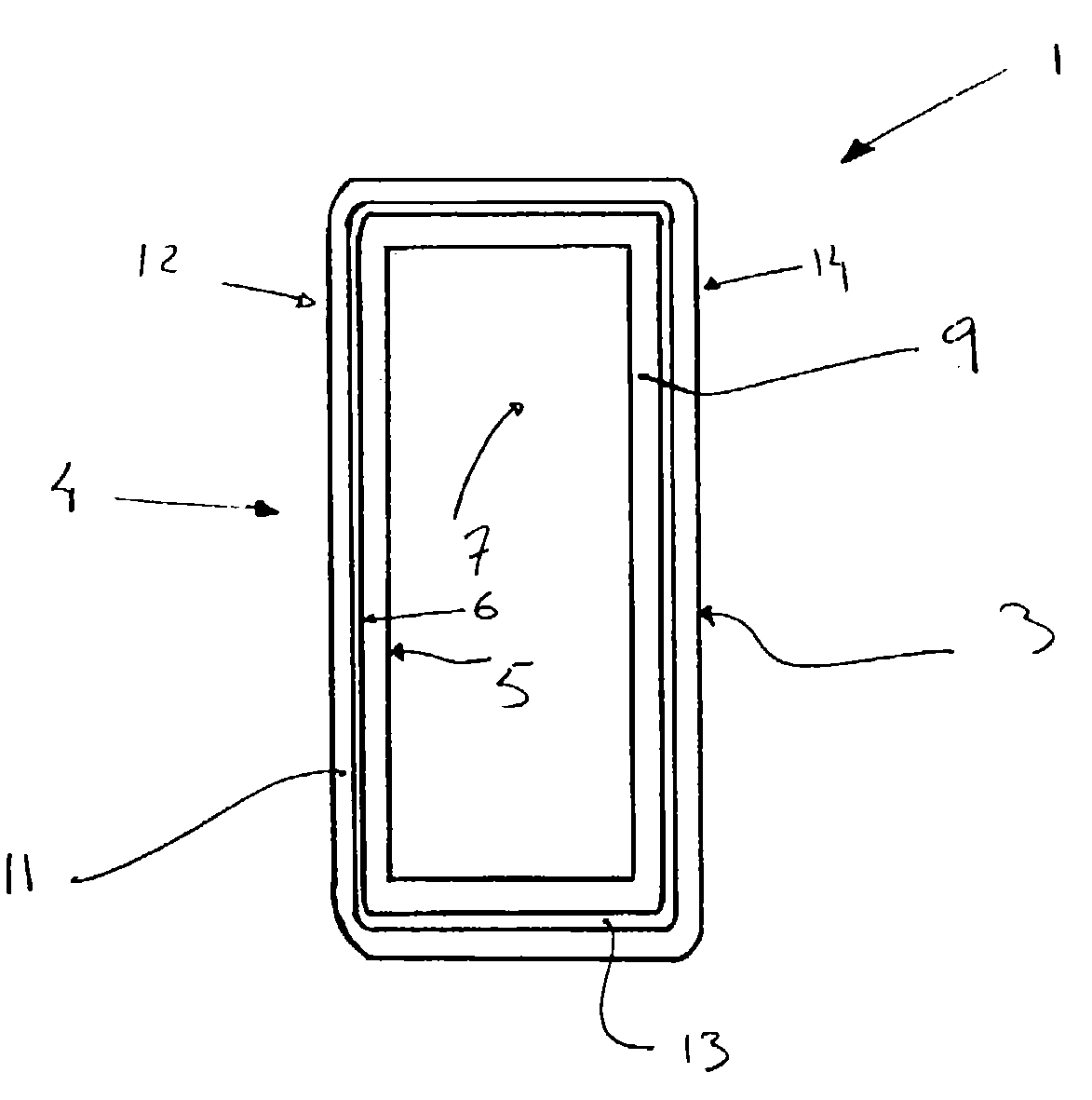
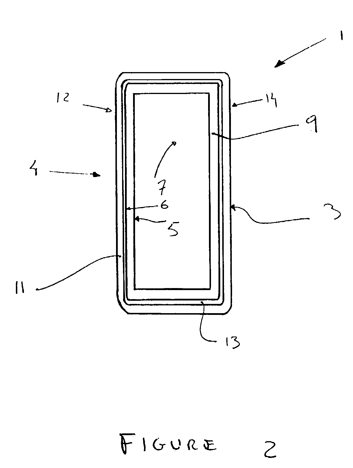
[0035]FIG. 2 illustrates a close-up of the cross-section of shaft 4 along section lines A—A of FIG. 1. As shown, the shaft construction is comprised of a number of layers, namely an inner layer 9 comprising an inside surface 5 and an outside surface 6. Further, the wall construction of shaft 4 comprises a viscoelastic layer 13 disposed adjacent to and abutting inner layer 9. Further, an outer layer 11 is disposed on an abutting viscoelastic layer 13. Viscoelastic layer 13 is shown contacting both the inner layer 9 and the outer layer 11.

[0036]As illustrated, viscoelastic layer 13 is applied to surface 6 of inner layer 9 once inner layer 9 has been constructed. As may be understood, final curing of inner layer 9 may not have been complet...


PUM

PropertyMeasurementUnit
Thicknessaaaaaaaaaa
Viscoelasticityaaaaaaaaaa

Abstract

The present invention discloses a composite hockey stick shaft having an elongated body having four side wall members, at least one said side wall members comprising an inner layer of fibers disposed within a matrix material, a layer of viscoelastic material anchored onto to the outside surface of said inner layer, an outer layer of fibers disposed within a matrix material, said outer layer being disposed on and abutting the outside of said layer of viscoelastic material.

Description

BACKGROUND OF THE INVENTION[0001]The present invention relates to sporting equipment shafts and in particular to shafts suitable for use in high-impact, high-velocity, and high wear and tear sports such as ice hockey, street hockey, in-line skate hockey, ringuette, field hockey, lacrosse and other such sports. The present invention, by way of example only, will be described hereinafter in relation to ice hockey sticks, but it is understood that the invention herein described and claimed may be suitably adapted to other shaft applications and in particular to other sports.[0002]At present, hockey sticks may be generally broken down into two broad categories, namely wooden hockey sticks, which shafts are generally made of wood such as any suitable hardwood, for example hickory, maple, etc., and composite sticks, which shafts are made of composite materials, such as carbon fiber, Kevlar™, fiberglass, and other such materials or combination of materials which are embedded in any one of ...

Claims


Application Information

Patent Timeline
IPC IPC(8): A63B59/14B29C44/02B29C65/02B29C70/08B29C70/44
CPCB29C70/086B29C70/446B29L2031/5227
Inventor BLOTTEAUX, RAY
Owner SPORT MASKA
Why Eureka
Try Eureka