Induction heating cooker

a technology of infrared sensor and infrared sensor, which is applied in the direction of electric/magnetic/electromagnetic heating, domestic stoves or ranges, lighting and heating apparatus, etc., can solve the problems of inability to detect the correct temperature using an infrared sensor having a wide view angle, and achieve the effect of reducing influence, reducing the temperature rise of the infrared sensor, and improving the accuracy of temperature detection by the infrared sensor

Active Publication Date: 2006-10-31
PANASONIC CORP
View PDF9 Cites 11 Cited by
  • Summary
  • Abstract
  • Description
  • Claims
  • Application Information

AI Technical Summary

Benefits of technology

[0013]In the foregoing structure, the presence of the waveguide allows reducing influence from infrared radiation other than that radiated from the pot base. The foregoing placement of the first and second magnetism-proofing units allows converging magnetic fluxes leaked from the heating coil to those magnetism-proofing units, so that self-heating of the waveguide due to the leakage magnetic fluxes can be reduced. This structure allows reducing a temperature rise of the infrared sensor due to radiation heat from the waveguide, so that an accuracy of temperature detection by the infrared sensor can be improved.

Problems solved by technology

However, in this conventional cooker, use of an infrared sensor having a wide view angle fails in detecting a correct temperature because the sensor is subjected to infrared rays other than that from the pot base.

Method used


Image

  • Induction heating cooker
  • Induction heating cooker
  • Induction heating cooker

Examples


first exemplary embodiment

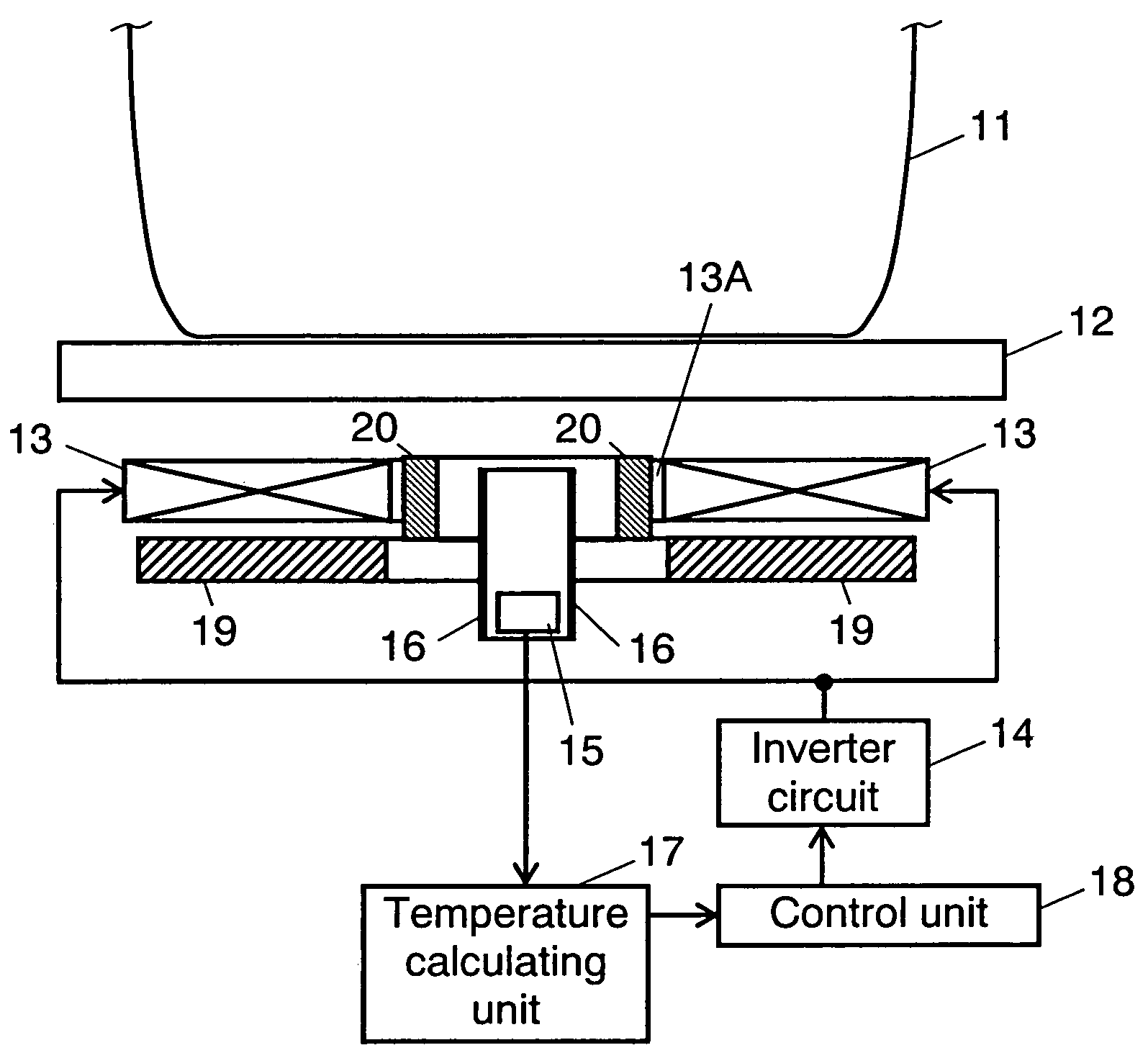
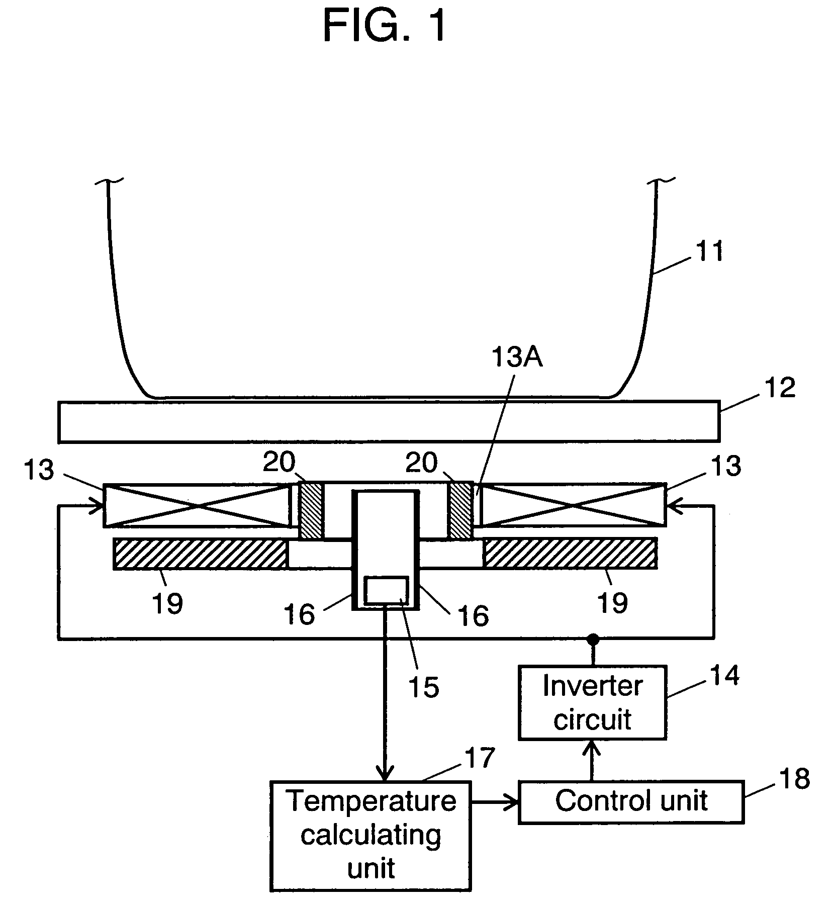
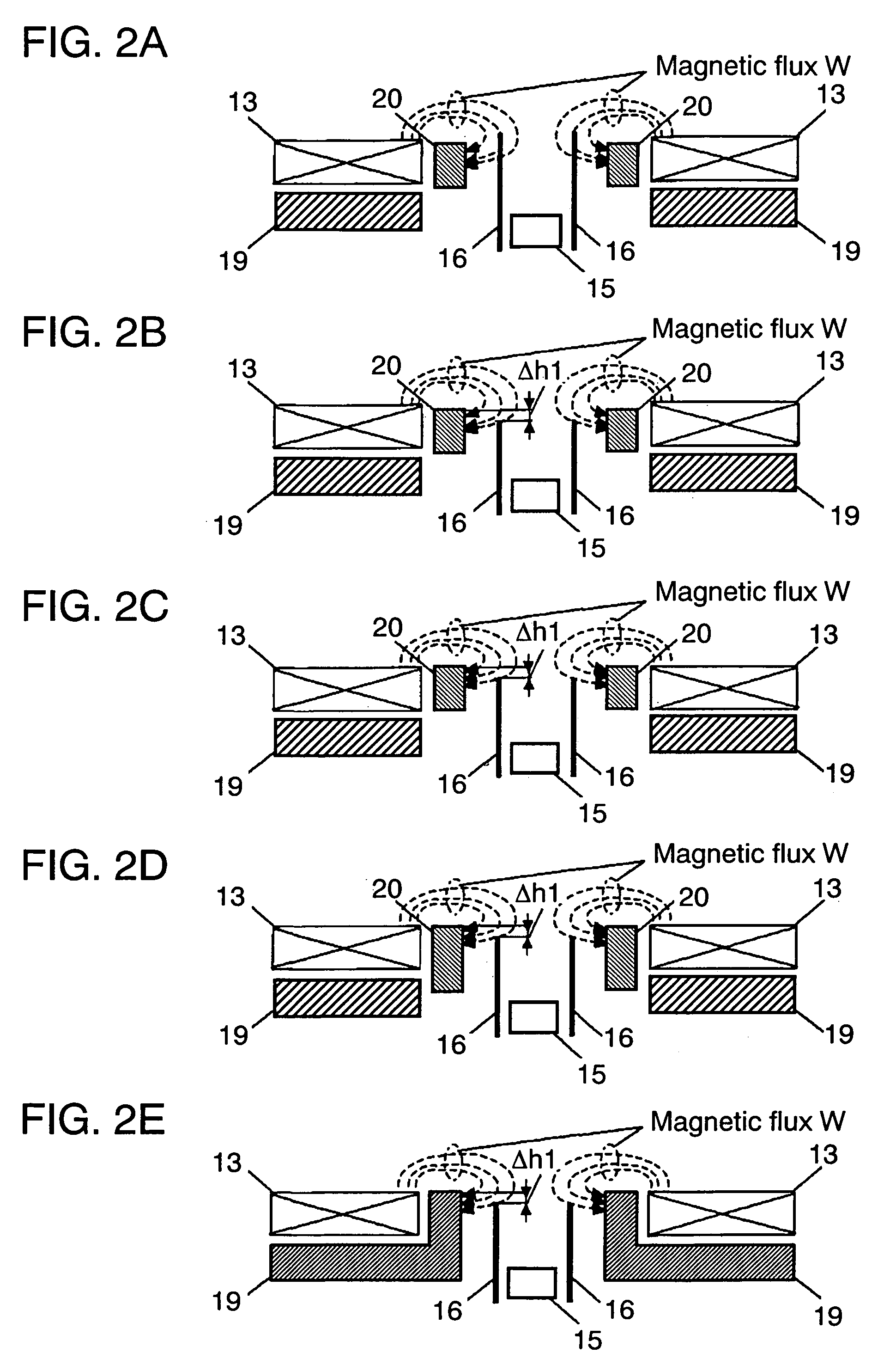
[0020]FIG. 1 shows a sectional view illustrating a structure of an induction heating cooker in accordance with the first exemplary embodiment of the present invention. FIG. 2A–FIG. 2E show a sectional view illustrating relations between a heating coil, a waveguide, and magnetism-proofing units of the induction heating cooker shown in FIG. 1.

[0021]A structure of the induction heating cooker of the first embodiment is described with reference to FIG. 1. Heating coil 13 has opening 13A at its center, and a winding wire wound around opening 13A. Running of a high-frequency current through coil 13 generates a high-frequency magnetic field, thereby providing load pot 11 placed on top plate 12 with induction-heating. Inverter circuit 14 supplies a high-frequency current to heating coil 13. Infrared sensor 15 is disposed under opening 13A and detects an intensity of infrared ray radiated from load pot 11. Temperature calculating unit 17 calculates a temperature of load pot 11 based on an ou...

second exemplary embodiment

[0034]FIG. 3 shows a sectional view illustrating a construction of the induction heating cooker in accordance with the second exemplary embodiment of the present invention. FIG. 4 shows a plan sectional view of a heat shielding unit used in the cooker shown in FIG. 3, and FIG. 5 shows a sectional view illustrating a relation between a heating coil, a waveguide, and magnetism-proofing units.

[0035]The construction of the cooker in this second embodiment is basically the same as that in the first embodiment, so that different points are detailed here. As shown in FIG. 3, the cooker is additionally equipped with cylindrical heat-shielding unit 21 for reducing a temperature change at the elements of infrared sensor 15. Heat shielding unit 21 is formed of non-magnetic metal of excellent heat conduction such as copper or aluminum for obtaining a uniform temperature. Unit 21 is disposed between waveguide 16 and second magnetism-proofing unit 20 and situated lower than an upper surface of ma...


PUM


Abstract

An induction heating cooker includes an infrared sensor for sensing an infrared intensity from a load pot, a waveguide for guiding infrared radiation from the load pot to the infrared sensor, a first magnetism-proofing unit and a second magnetism-proofing unit for reducing magnetic fluxes leaking from a heating coil. Placement of the waveguide at a position lower than an upper surface of the second magnetism-proofing unit reduces self-heating of the waveguide due to magnetic flux supplied from the heating coil. As a result, a temperature rise of the infrared sensor due to radiation heat from the waveguide can be reduced, and an accuracy of sensing a temperature by the infrared sensor can be improved.

Description

[0001]This application is a U.S. National Phase Application of PCT International Application PCT / JP2004 / 010532, filed Jul. 16, 2004.TECHNICAL FIELD [0002]The present invention relates to induction heating cookers employing an infrared sensor.BACKGROUND ART [0003]One of conventional induction heating cookers is disclosed in Japanese Patent Unexamined Publication No. H03-184295, and this cooker employs an infrared sensor for detecting a temperature of a load pot. The infrared sensor directly detects an infrared ray radiated from the pot base, so that a temperature detection of excellent thermal response can be achieved. However, in this conventional cooker, use of an infrared sensor having a wide view angle fails in detecting a correct temperature because the sensor is subjected to infrared rays other than that from the pot base.DISCLOSURE OF INVENTION [0004]The induction heating cooker of the present invention comprises the following elements:[0005]a heating coil for heating a load p...

Claims


Application Information

Patent Timeline
Patent Type & Authority Patents(United States)
IPC IPC(8): H05B6/06F24C7/02H05B6/12
CPCH05B6/062H05B2213/07H05B6/1254Y02B40/00H05B6/12H05B6/06
Inventor TOMINAGA, HIROSHIISHIMARU, NAOAKITAKADA, KIYOYOSHIIZUTANI, TAMOTSU
Owner PANASONIC CORP
Why Eureka
Try Eureka