Scanning probe with digitized pulsed-force mode operation and real-time evaluation

a scanning probe and pulsed-force mode technology, applied in the direction of scanning probe microscopy, electrical/magnetic measuring arrangement, instruments, etc., can solve the problems of inability to simple allocate to a physical variable, and inability to solve simple mechanical specimen properties. , to achieve the effect of sufficient precision and short period of tim

Inactive Publication Date: 2006-10-31
WITEC WISS INSTR & TECH
View PDF9 Cites 65 Cited by
  • Summary
  • Abstract
  • Description
  • Claims
  • Application Information

AI Technical Summary

Benefits of technology

[0032]It is thus the object of the present invention to provide an imaging method for an apparatus comprising a scanning probe which allows on the one hand recording a plurality of physical propert

Problems solved by technology

The disadvantage of this imaging method is that when moving the scanning probe which is in contact with the surface of the specimen piece, shearing forces will occur which deform the surface of soft specimens such as polymeric or biological systems or can even destroy the same.
One disadvantage of this method is however that the resolution decreases with increasing distance between scanning probe and specimen surface and no mechanical specimen properties can be examined.
The “intermediate-contact-mode” method comes with the disadvantage that the two variables, amplitude and phase shift, depend on a plurality of variables, so that a simple allocation to a physical variable is not possible.
The disadvantageous aspect in this method is that the scanning speed for recording an image is very low.
The disadvantageous aspect in the imaging method of a

Method used


Image

  • Scanning probe with digitized pulsed-force mode operation and real-time evaluation
  • Scanning probe with digitized pulsed-force mode operation and real-time evaluation
  • Scanning probe with digitized pulsed-force mode operation and real-time evaluation

Examples


Embodiment Construction

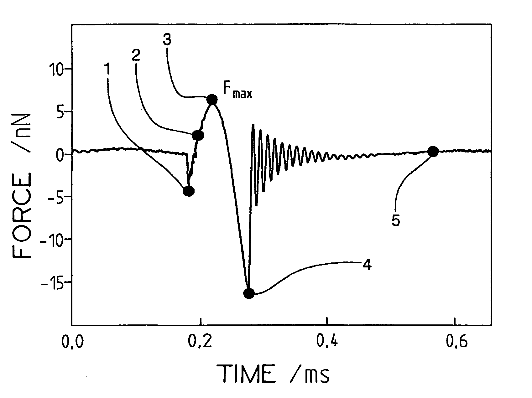
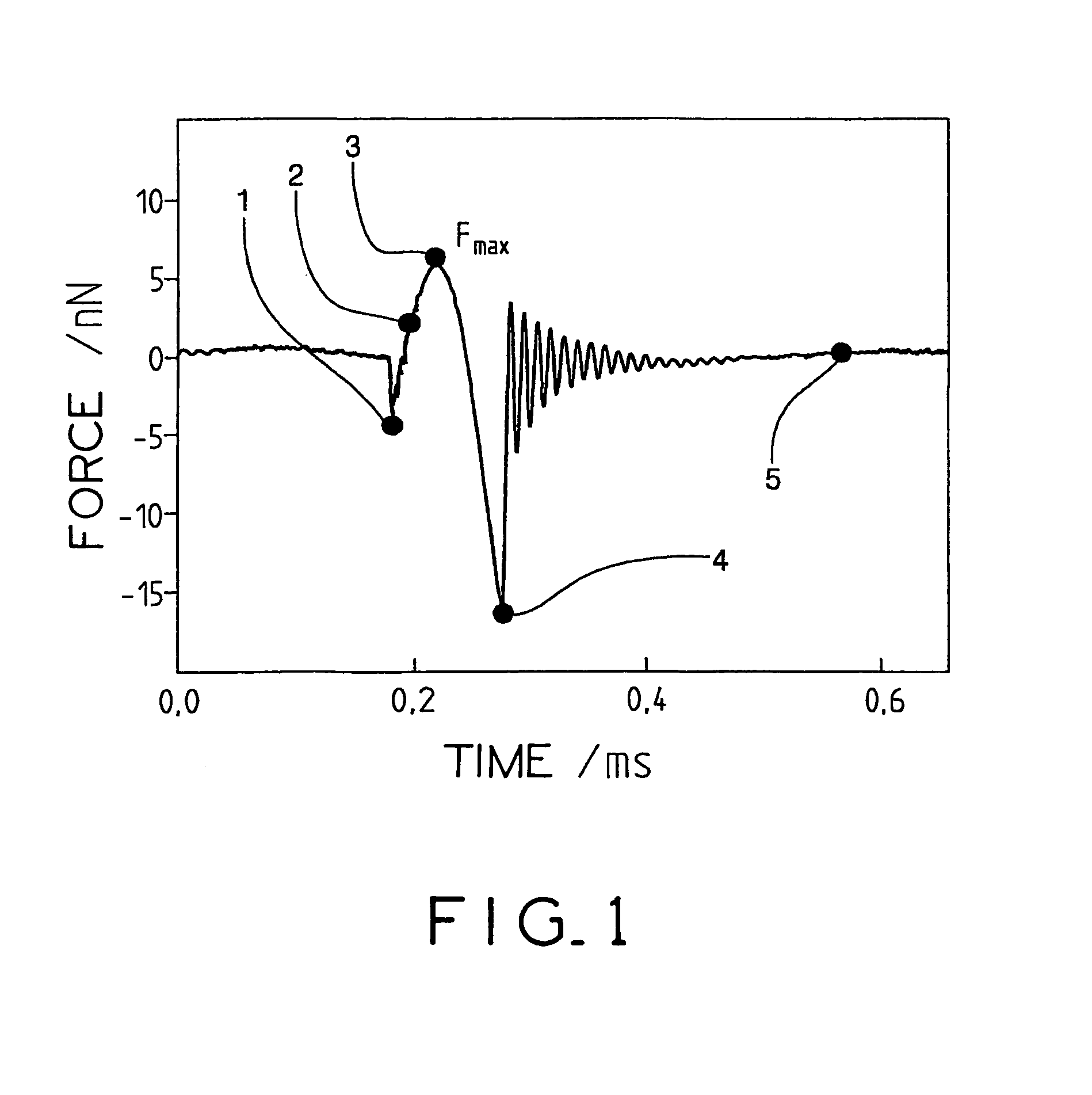
[0073]FIG. 1 shows the characteristic progress of a force-time curve as obtained after passing through an oscillation period of a scanning probe, which in the present case is a probe tip arranged on a beam. The oscillation amplitude of the oscillation of the scanning probe tip as excited by means of a piezoelectric element lies between 10 and 500 nm and the oscillation frequency between 1 Hz and 5 kHz, and in the present case in the region of 1 kHz.

[0074]FIG. 1 clearly shows the characteristic regions of the force-time curve which arises., when excited, perpendicular to the specimen surface. Said regions can be used for determining the characteristic variables and, when applied to the scanned region, lead to the different forms of image of the specimen surface.

[0075]The function as illustrated in FIG. 1 is already standardized on the base or zero line, which means that the force value of the base line of the scanning probe is set to zero. The base line can be determined in such a wa...


PUM


Abstract

The invention relates to a method for creating the image of a sample surface to be analyzed, with a resolution which is better than 1 μm laterally in relation to the sample surface and better than 100 nm vertically in relation to said surface. According to the invention, the surface is scanned on a point-by-point basis by a scanning probe, the distance between the scanning probe and the sample surface at each scanning point being periodically modulated, in such a way that a force-time curve of the probe is produced for this point. The force-time curve is recorded at each scanning point, digitized using an A/D converter, evaluated online in real-time and stored, together with the entire data stream, in a first area of a memory device. One or several characteristic variables of the force-time curves are determined for each scanning point from the real-time evaluation results and the stored digitized force-time curves and an image of the sample surface is obtained from said characteristic variables of the scanning points.

Description

BACKGROUND OF THE INVENTIONPrior Art[0001]The invention relates to a method for producing the image of a surface of a specimen to be examined with a resolution which is better than 1 pm laterally to the surface and better than 100 nm perpendicularly to the surface, with a scanning probe scanning the surface point by point and the distance between the scanning probe and the specimen surface being modulated at each scanning point, thus leading to a force-time curve. The invention also provides a scanning probe microscope for performing such a method.[0002]A large number of methods for imaging the surfaces of specimen pieces by means of scanning probes have already been described in the state of the art.[0003]One possibility for examining a specimen surface and for producing a surface image by means of a scanning probe is that the scanning probe is brought into contact with the surface of the specimen and the surface of the specimen is then scanned. Such an imaging method is known as “...

Claims


Application Information

Patent Timeline
IPC IPC(8): G01N23/00G01B7/34G01Q10/00G01Q10/06G01Q20/02G01Q30/04G01Q60/32G01Q60/34G21K7/00
CPCB82Y35/00G01Q10/06G01Q30/04G01Q60/32G01Q60/34
Inventor SPIZIG, PETERSANCHEN, DETLEFFORSTNER, JORGKOENEN, JOACHIMMARTI, OTHMAR
Owner WITEC WISS INSTR & TECH
Why Eureka
Try Eureka