Illuminated sign for traffic control and method for functional monitoring of such a sign

a technology of illumination and traffic control, applied in the direction of process and machine control, identification means, instruments, etc., can solve the problems of inadequate light intensity or not being displayed, the sign to be produced by them becoming distorted, and it is not possible to use led technology

Inactive Publication Date: 2006-10-31
SIEMENS AG
View PDF22 Cites 29 Cited by
  • Summary
  • Abstract
  • Description
  • Claims
  • Application Information

AI Technical Summary

Benefits of technology

[0015]One part of the object according to an embodiment of the invention is achieved by an illuminated sign. By limiting the current through the light-emitting diodes that is built up after the light source has been switched on, on the basis of the time duration or level, the light emission which occurs directly from the LEDs can be restricted such that it is no longer perceptible for a viewer, even in darkness. This avoids light flashes that would disturb those in the traffic. The rise in the current through the light-emitting diodes is used as the serviceability criterion.
[0016]In one preferred refinement of an embodiment of the invention, the monitoring device for the illuminated sign has a switching device for switching off the current flow, once it has been switched on, when the current level reaches a predetermined threshold value. The electrical current flowing through the light-emitting diodes is in this case limited by presetting a maximum threshold value at which the LED current level once it is switched off has been built up. Parts of the existing current monitoring device from the incandescent lamp technology can advantageously be used for the circuitry implementation of this form of current regulation, thus minimizing the circuit cost.
[0018]In one preferred embodiment of the invention, the monitoring device is also designed to measure the voltage which is dropped across light-emitting diodes when current is flowing through them. This separate additional monitoring of the voltage makes it possible to detect a failed light-emitting diode despite the LED current flow, for example in the event of a short. This improves the reliability of the functional testing of an illuminated sign according to an embodiment of the invention.
[0023]In one advantageous refinement of the method according to an embodiment of the invention, the current flows when the light-emitting diodes are in an inactive state, or periodically in an inactive phase. This allows the functional monitoring to be carried out not only when the illuminated sign is not in operation—even for a lengthy time period of several months—but also during operation, by switching off the regular LED current flow periodically for a short phase, in which the even shorter test current flow then takes place.

Problems solved by technology

Incandescent lamps can fail by a short or discontinuity, thus resulting in a sign to be produced by them becoming distorted, with inadequate light intensity or not being displayed at all.
One problem is that signs which can be produced by LEDs have until now been capable of being monitored only when they are in the switched-on state.
It has therefore not been possible to use LED technology for safety-relevant signs, whose serviceability must also be monitored when they are switched off.
Owing to the effectively inertia-free conversion of current to light in LED light sources, a functional test analogous to the so-called cold lamp test was not feasible without production of disturbing, and thus unacceptable, light flashes.
Signs with functional monitoring which produce sufficiently short and weak current pulses and can reliably monitor them have not until now been feasible at an acceptable complexity level.

Method used


Image

  • Illuminated sign for traffic control and method for functional monitoring of such a sign
  • Illuminated sign for traffic control and method for functional monitoring of such a sign
  • Illuminated sign for traffic control and method for functional monitoring of such a sign

Examples


Embodiment Construction

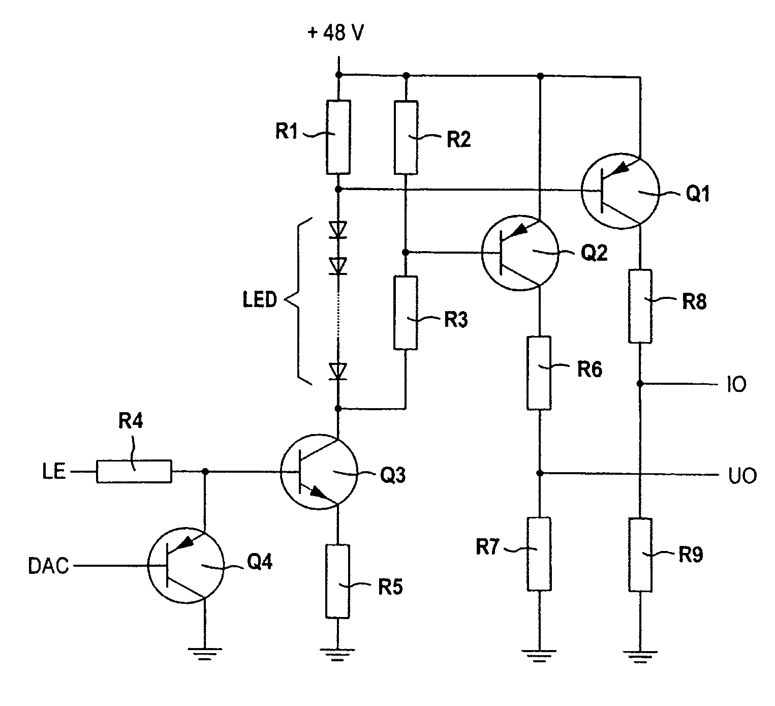
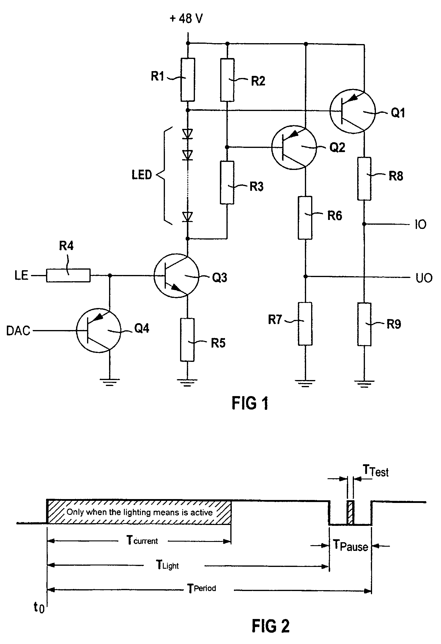
[0028]An illuminated sign according to an embodiment of the invention, for example a changing traffic sign for displaying different traffic signs alternately, is produced, for example, in an outdoor system which is in the form of a display gantry above roadways. The outdoor system has a mains connection for supplying voltage to the LED chains. For this purpose, a commercially available industrial switched-mode power supply, for a DC voltage of 48 V and having an input rating of 100 W, is used. This is connected via a CAN bus to a roadway section station which includes a modem as well as a control and a master module.

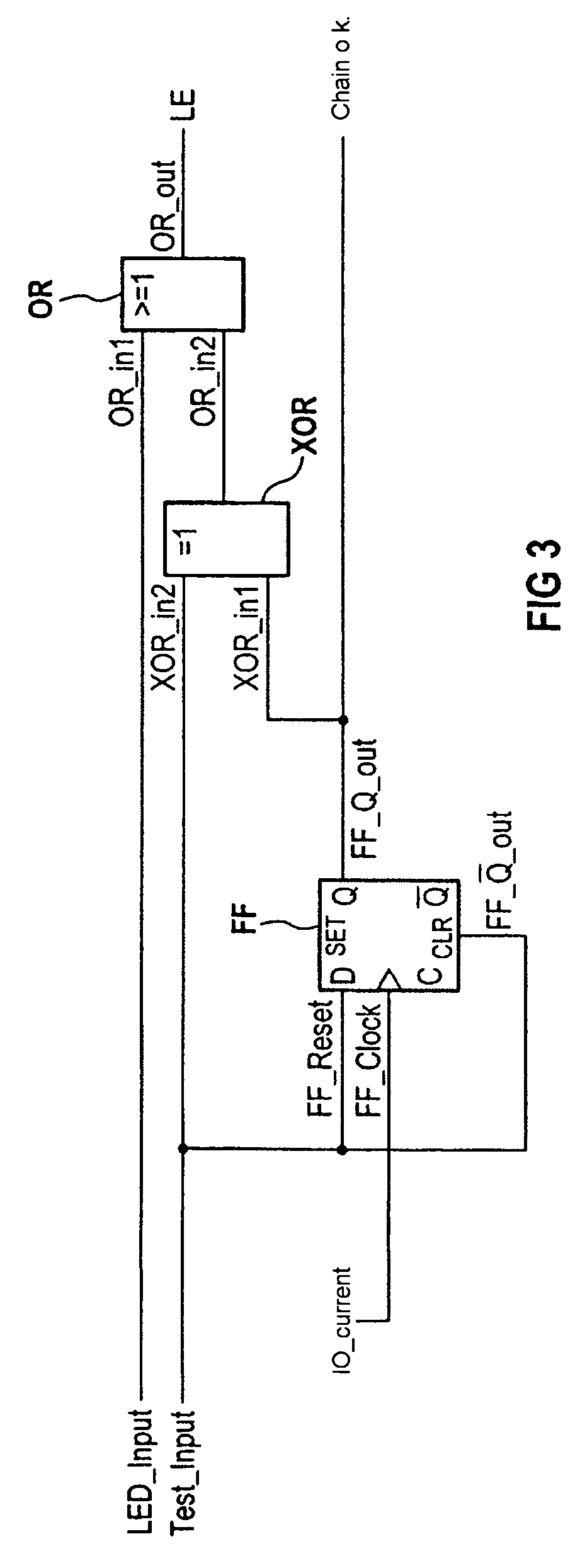
[0029]By way of example, 32 LED chains, subdivided into four groups of eight each, can be driven via a common drive assembly. The drive assembly contains a digital part and an analog part. The digital part has modules for initialization, assembly identification, read / write logic, a test register, the enabling logic for the normal mode and the test mode, the LED current s...


PUM


Abstract

An illuminated sign is for traffic control, in particular for road traffic, and includes light sources for generation of the sign and a monitoring device for functional monitoring of the light source. The light sources are embodied as light diodes and the monitoring device is embodied as a device for the limited current loading of the light diodes. The functional monitoring of said sign can be achieved with reasonable technical requirements in both the deactivated and activated state thereof.

Description

[0001]This application is the national phase under 35 U.S.C. § 371 of PCT International Application No. PCT / DE02 / 02877 which has an International filing date of Aug. 5, 2002, which designated the United States of America and which claims priority on German Patent Application number DE 101 40 331.3 filed Aug. 16, 2001, the entire contents of which are hereby incorporated herein by reference.FIELD OF THE INVENTION[0002]The invention generally relates to an illuminated sign for traffic control, in particular for road traffic. It further generally relates to a method for functional monitoring of such a sign.BACKGROUND OF THE INVENTION[0003]Signs of widely differing types and importance are generally used for controlling traffic, in order to assist the smooth handling of the traffic. This applies to marine navigation, to aircraft, for example to airports, as well as to all rail traffic, but in particular to road traffic.[0004]Owing to the continuously rising amount of traffic, ever more ...

Claims


Application Information

Patent Timeline
Patent Type & Authority Patents(United States)
IPC IPC(8): G08G1/095G09G3/00H05B37/03H05B44/00
CPCG09G3/006H05B33/0887H05B33/0893H05B37/03H05B45/50H05B45/58H05B47/20
Inventor HERING, BERNHARDSCHIERJOTT, RUDOLFTREFFER, GERHARD
Owner SIEMENS AG
Why Eureka
Try Eureka