
Rotating scan self-cleaning camera

a self-cleaning and camera technology, applied in the field of rotating scan self-cleaning cameras, can solve the problems of lack of resolution, inability to achieve the most realistic picture of the surrounding scene, and the design of rotary scanning cameras also does not address other important design considerations, etc., to achieve the effect of improving resolution, simplifying recording mechanism, and increasing resolution

Inactive Publication Date: 2006-10-31
IMMERSIVE LICENSING
View PDF3 Cites 60 Cited by
  • Summary
  • Abstract
  • Description
  • Claims
  • Application Information

AI Technical Summary

Benefits of technology

[0016]F. It is also an object of this invention to improve the stability of a camera by using rotation. The advantage of the present invention over the SteadiCam approach is the elimination of external gyroscopes, a lighter apparent weight due to aerodynamic lift, and greater axial stability due to higher angular momentum relative to the overall weight of the camera.
[0017]G. It is also an object of the invention to dynamically adjust the convergence of a panoramic stereoscopic view in order to to focus viewing on objects at selected distances. No prior art addresses this problem.
[0018]H. It is also an object of the present invention to provide a convenient and cost-effective method and apparatus for recording high-quality scan image data on film. No prior art has been able to accomplish this.
[0019]I. It is also an object of the present invention to enable smooth and balanced operation of a rapidly rotating camera using internal film reels. The prior art does not address the optimal arrangement for motion and stereoscopic recording.

Problems solved by technology

What these solutions lack is an effective way to record not only the appearance of the real world in motion through the slit, but also to use that information to create a stereoscopic image of the entire field of view.
Without that stereoscopic information, the most realistic picture of a surrounding scene is not possible, as well as other applications such as rangefinding that depend on parallax offsets between different points of view.
Existing designs for rotary scanning cameras also do not address other important considerations of design needed for successful use of the camera in the field.
These include the noise that the camera makes, which affects whether sound can be recorded effectively together with the picture, the weight of the unit, which affects whether a camera operator can carry it, and the stability of the camera, which is important for steady, natural motion pictures when the camera moves through a scene in the course of recording.

Method used


Image

  • Rotating scan self-cleaning camera
  • Rotating scan self-cleaning camera
  • Rotating scan self-cleaning camera

Examples


Embodiment Construction

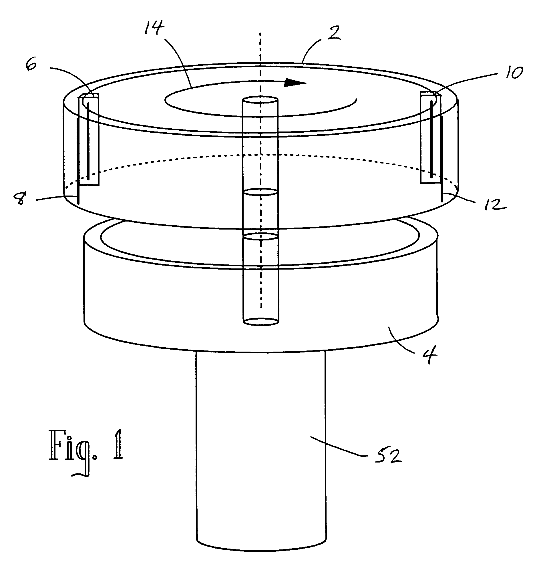
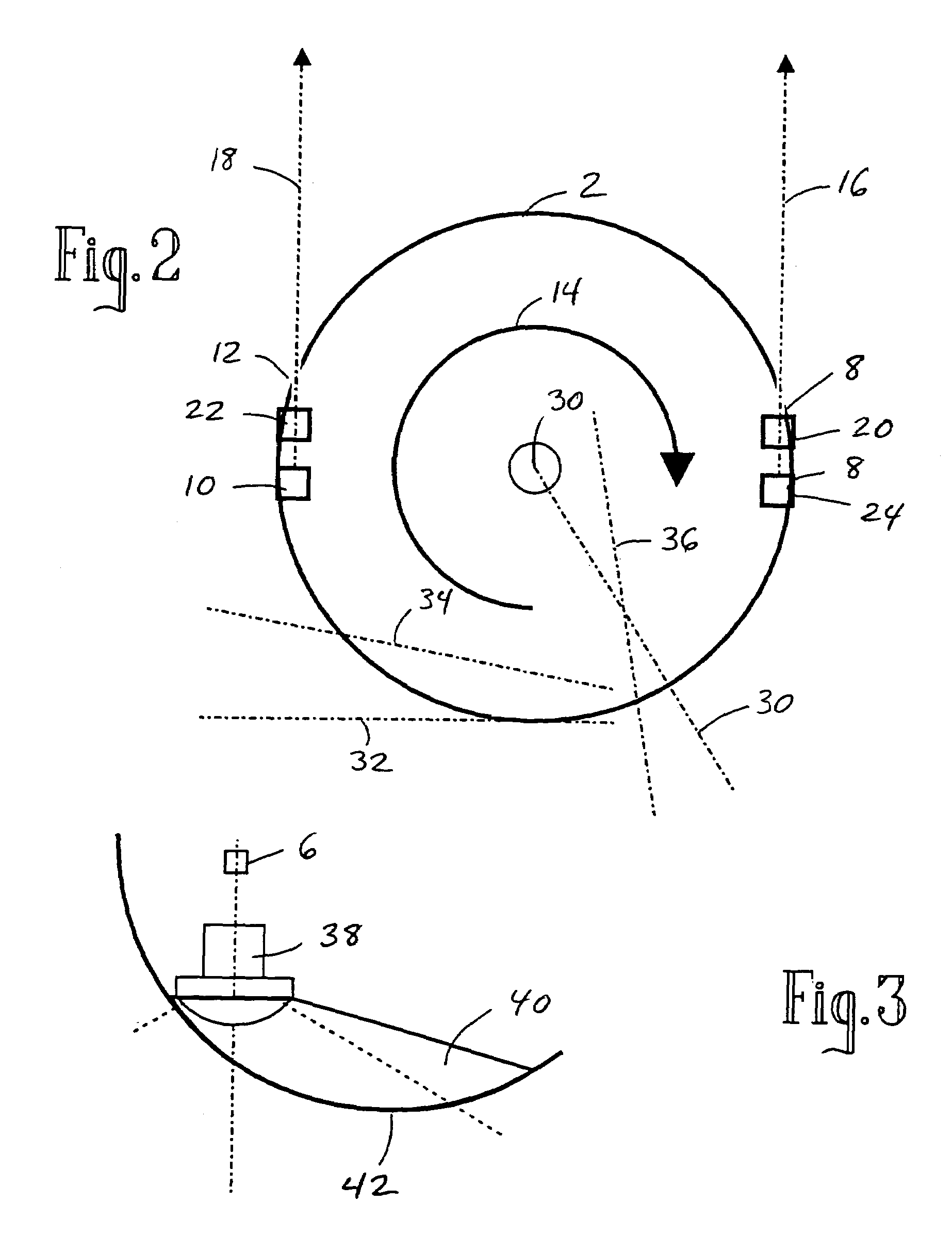
[0036]A rotary scanning camera of a novel design offers improved performance in capturing a panoramic surrounding scene. One or more line-scan sensors are used in a sweeping recording of a surrounding scene. The scan can be of a partial rotation or of one or more full rotations. Unlike the prior art, these sensors each have an optical axis that does not intersect the axis of rotation.

[0037]In the preferred embodiment, a rotating drum holds two line-scan devices for scanning the appearance of a surrounding field of view from stereoscopically separated viewpoints, with each optical axis on approximately a tangent line to the cylinder. This-creates a pair of offset sweeping scans that record objects in the surrounding view from one, then the other point of view, thereby creating an effective parallax separation in the recorded images. This parallax separation is the same for every point in the rotation of the drum.

[0038]FIG. 1 shows an oblique view of a rotatable scan camera according ...


PUM


Abstract

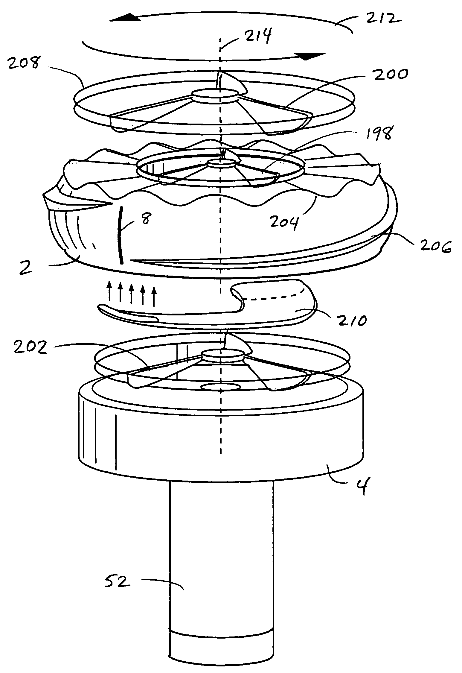
A scanning camera with a rotating drum has one or more sensors characterized by a non-radial optical axis. With two sensors on opposite sides of the drum and facing in substantially the same direction, stereoscopic recording of a panorama is accomplished as the drum rotates. Rapid rotation of the scanning camera produces panoramic motion picture recording, with the final frame speed dependent on the sensitivity and speed of the sensor, the resolution desired, and the capabilities of the recording device. The preferred embodiment employs rotating fisheye lenses for a substantially full-sphere field of view. Streamlining of the lens elements on the drum surface is described for quiet operation of the camera, even at high rotation speeds. The rapid rotation of the drum characteristic of motion picture frame rates can improve both the stability and portability of the camera. The gyroscopic effect of the rotating weight of the drum can increase the stability of the camera, and the apparent weight of the camera can be reduced by the lifting effect of aerodynamic elements such as rotors added to the rotating drum. The adjustment of convergence are described that improve the viewing of stereoscopic images. Additional sensors in the same arrangement are used to increase resolution through multiplexed recording of the image data. Recording image information using film, either internal or external to the camera drum, is also described as a cost-effective alternative to digital media storage.

Description

[0001]This Application is a continuation of application Ser. No. 09 / 505,601, filed Feb. 16, 2000 now abandoned. This invention generally relates to a panoramic image reproduction system, and in particular to the use of rotary scanning elements in a camera design. This invention also relates to the use of aerodynamic elements to reduce the apparent weight and provide other benefits to a rotating apparatus, and to the use of gyroscopic stabilization of a camera platform.BACKGROUNDField of the Invention[0002]Description of the Prior Art[0003]Cameras for capturing still or motion pictures of the external world have usually used an area array sensor, such as a 640×480 Charge-Coupled Device (CCD) for NTSC video images. These area sensors use a rectangular or square area of light-sensitive elements and expose them all at once. New forms of Complementary Metal Oxide Semiconductor (CMOS) sensors for cameras are also being made in a variety of resolutions.[0004]Linear scan sensors are also be...

Claims


Application Information

Patent Timeline
Patent Type & Authority Patents(United States)
IPC IPC(8): H04N7/00H04N5/225H04N13/239H04N13/243
CPCH04N5/2251H04N5/23238H04N13/0239H04N13/0242G03B37/02H04N13/243H04N13/239H04N23/50H04N23/698
Inventor MCCUTCHEN, DAVID
Owner IMMERSIVE LICENSING
Learn More