Rendering system and method for images having differing foveal area and peripheral view area resolutions

a technology of viewing system and image, applied in the field of remote viewing system and remote image processing, can solve problems such as the change of viewing angle of the remote camera, and achieve the effects of reducing image transmission bandwidth and time requirements, shortening latency, and reducing image data siz

Active Publication Date: 2006-10-31
TOBII TECH AB
View PDF20 Cites 47 Cited by
  • Summary
  • Abstract
  • Description
  • Claims
  • Application Information

AI Technical Summary

Benefits of technology

[0018]To reduce the image transmission bandwidth and time requirements and to shorten the latency from the user's eye moving to presenting an updated image to the user, a special image processing method is employed by the server which includes dividing the full-resolution image into a foveal area and a peripheral area. The peripheral area data is then compressed or reduced in resolution, thereby reducing the image data size. This image is then transmitted to the client and displayed to the user. Later, the full resolution data from the peripheral area of the image is transmitted to the client machine so that the full image may be rendered in original full resolution.
[0019]The present invention provides a method for rendering an image in two parts——foveal and peripheral—using two separate cameras, one for capturing the higher-resolution foveal area and another for capturing the lower resolution peripheral area. This avoids the need for first capturing a high-resolution image of the entire field of view, separating it into peripheral and foveal, and then compressing the peripheral view data. Instead, two cameras are pointed at the same point of interest. A first camera with higher resolution imaging sensors or having a telephoto lens is used to capture a high resolution image of the center, foveal area of the field of view. The second camera, which has a lower resolution imaging sensor or wide angle lens, is used to simultaneously capture the entire field of view. The data from the first camera representing the foveal view is then transmitted with priority to the remote viewer.

Problems solved by technology

As such, movements of the client computer user's eyes result in changes in viewing angle of the remote cameras.

Method used


Image

  • Rendering system and method for images having differing foveal area and peripheral view area resolutions
  • Rendering system and method for images having differing foveal area and peripheral view area resolutions
  • Rendering system and method for images having differing foveal area and peripheral view area resolutions

Examples


Embodiment Construction

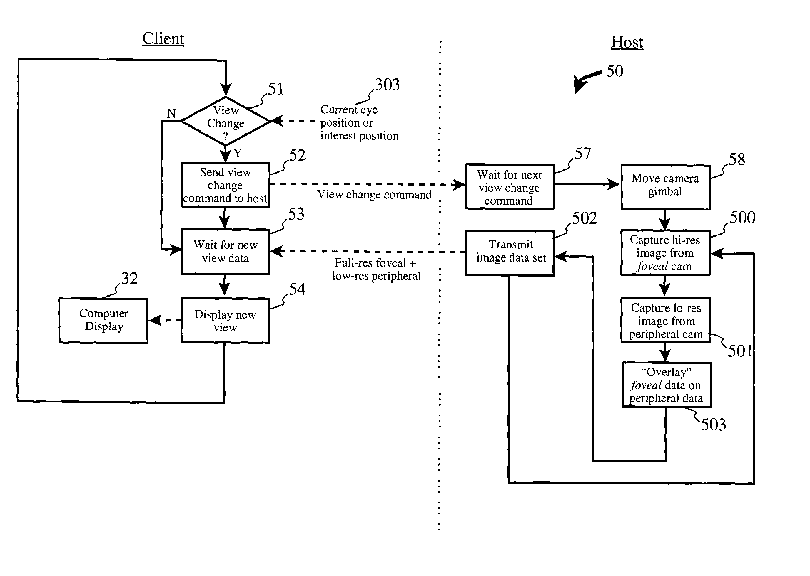
[0028]With the well-known present day interactive Internet technology, it is possible to have remote web cams and other such viewing devices. The visual resolution of these systems is typically quite limited, mostly due to bandwidth limitations through the internet. The present invention is preferrably realized in conjunction with or as an enhancement to the invention of the related (and incorporated) patent application.

[0029]In a first advantage of the related invention as described in the related patent application, it is possible to have higher resolution images and stereoscopic remote viewing, as well. In a second advantage of the related invention, it is possible to control the remote viewing angle using eye movements rather than a joystick, on-screen icons, or other type of pointing device.

[0030]The present invention enhances the related invention by using two cameras of differing lens configurations (e.g. telephoto and wide angle), differing image capture resolutions, or a si...


PUM


Abstract

A client-server arrangement for camera viewing using digital cameras across a computer network. A camera server controls a motorized gimbal which determines the viewing angles of a set of cameras according to signals from a client computer which is equipped with an eye movement tracking system. Movements of the viewer's eyes result in changes in viewing angle of the remote cameras. A high resolution foveal field of view image centered on the user's point of interest is captured and overlaid on a lower resolution full filed of view image, rendering a combined image having a low resolution peripheral area and a high resolution foveal area, and being significantly reduced in size compared to a full resolution, full field of view image. This combined image is transmitted to the client for display to the user.

Description

CROSS-REFERENCE TO RELATED APPLICATIONS (CLAIMING BENEFIT UNDER 35 U.S.C. 120)[0001]This patent application is related to U.S. patent application Ser. No. 10 / 127,068, filed on Apr. 4, 2002, by Viktors Berstis.FEDERALLY SPONSORED RESEARCH AND DEVELOPMENT STATEMENT[0002]This invention was not developed in conjunction with any Federally sponsored contract.MICROFICHE APPENDIX[0003]Not applicable.INCORPORATION BY REFERENCE[0004]The related U.S. patent application Ser. No. 10 / 127,068, filed on Apr. 4, 2002, by Viktors Berstis, is hereby incorporated by reference in its entirety, including figures.BACKGROUND OF THE INVENTION[0005]1. Field of the Invention[0006]This invention relates to the arts of remote viewing systems and remote image processing, for purposes such as remote quality inspection, maintenance service actions, medical procedures, and the like.[0007]2. Background of the Invention[0008]Remote viewing of camera images is well known in the art, from the proprietary arrangements u...

Claims


Application Information

Patent Timeline
Patent Type & Authority Patents(United States)
IPC IPC(8): H04N5/222G09G5/00H04N5/232H04N5/265H04N7/173H04N7/18
CPCH04N5/23206H04N5/265H04N7/173H04N7/181H04N21/2187H04N21/2393H04N21/4143H04N21/4223H04N21/6587H04N23/661H04N23/61H04N23/63
Inventor BERSTIS, VIKTORS
Owner TOBII TECH AB
Why Eureka
Try Eureka