Method for enhancing object-oriented programming through extending metadata associated with class-body class-head by adding additional metadata to the database

a technology of object-oriented programming and database, applied in the field of object-oriented programming environment, can solve the problems of increasing complexity, requiring more from, and imposing more on, and innovation in the modern business world is often an unquenchable necessity, and conventional software development is itself often a complex problem

Active Publication Date: 2006-10-31
CALLAHAN CELLULAR L L C
View PDF45 Cites 61 Cited by
  • Summary
  • Abstract
  • Description
  • Claims
  • Application Information

AI Technical Summary

Benefits of technology

[0241]FIG. 8-A is a block diagram illustrating an embodiment of the hierarchical relationship of the three levels, shown in FIGS. 5–7, of the components used to create an application using the present invention. The Software Catalog 801 that contains an application definition is at level 1. The Application Table 802 that contains the class-head definition is at level 2. The Class Table 801 that contains the class-members' definition is at level 3. One advantage of the present invention over traditional object-oriented programming is that it adds information about the application to each object used. Having the characteristics for each application as “Application Head” defined separately in a table allows creating inheritances between applications, classifying the objects according to their application and the possibility to create parameterized applications. For example, a common object module used by two applications can have its behavior dependent on the application that calls this object. This further increases the modularity reusage of objects.
[0242]FIG. 8-B is a schematic block diagram showing an embodiment of the similarity between the metadata hierarchy of a database and a software application embodiment of this invention. An embodiment of the database includes a data warehouse 810, a database 812, a table 816, and a column 820. The software application includes a software catalog 822, an application 824, a class 826, and a member 828.
[0243]FIG. 9 is a flowchart further illustrating an embodiment of the hierarchical relationship of the three levels, shown in FIGS. 5–7, that compose the components of an application, and their relationship with the document that contains the persistent objects created by an end-user. The flowchart is subdivided into two stages: the “Design Stage” and the “Run-time Stage.”
[0244]The Design Stage is where an application modeler / domain expert of an application fills the tables with information. This stage contains the details of the three levels defined in FIG. 8-A. Each level has a metatable 901, 921, 931 that defines the tables 902, 922, 932 which contain the records 903, 923, 933 for each Application, Class or Member as designed by the application modeler / domain expert.
[0245]The Run-time Stage is where an end-user instantiates an object according to his or her specification 908 as designed by the application modeler / domain expert in the design stage. The objects instantiated 916 are placed as records 906 in the Objects' Data Table 905 which is located in a document folder 911 that is specified by an end-user. In one embodiment, only the fields 907 (attributes) of the object which have scope-level equal to “Instance-Level” are stored. The Document Manager Object 904 is an object independent of the data application, and has a Layout relationship 912, a Layer relationship 915 and other common properties' relationship 914. The Document folder 911—which can be a folder or an archive file—the Layer 915 and the layout 912 are created, defined and selected by an end-user prior to instantiating the objects 908. The entities placed in the Data Table 905 have complex unique IDs which are composed of the current application (AID), the current class (OID), the current layout (LID), and the current entity unique ID (EID). This design enables placing entities in a document having different applications and different layouts or space model.
[0246]To increase modularity of software programs and to extend the documents' capabilities to include instances created from several Data Applications, one embodiment of the present invention divides a created program into two separate objects simultaneously loaded at run-time: (a) the “Document Manager Object” and (b) the current “Data Object.” These objects work together at run-time, each with a specific task, as follows:

Problems solved by technology

Innovation in the modern business world is often an unquenchable necessity which demands more from, and imposes more complexity upon, software.
Conventional software development is itself frequently a complex process typically consisting of authoring source code using a particular programming language.
That is, using a particular OOPL typically requires thorough familiarity with, and adherence to, grammatical rules, syntax and language for that OOPL, and written code can quickly become voluminous and hard to manage for a software project.
As a result, the development, design, comprehension and / or maintenance of software is often burdensome and difficult.
Further, software programs are conventionally compiled and delivered in binary format, which cannot be comprehended or modified.
Finally, OOPLs typically do not support multi-applications documents.
Thus, an expert in a particular field (i.e., a domain expert) or business usually cannot read, write, customize, enhance or modify an object-oriented program that the domain expert uses for personal or business computing.
However, software development continues to be done in the traditional, difficult, time-consuming, and costly way of text-based source code.
Unfortunately, the voyage throughout the lifecycle of any software project using traditional development tools is, more often than not, a difficult and costly one—inviting complexity with maybe a million lines of code, lowering productivity between developers trying to make the “puzzle fit,” increasing costs, decelerating time-to-market, and widening the chasm between software development and domain knowledge.
And, as generally difficult as it may be for a professional programmer to design, develop, deploy and manage software, it is nearly impossible for a domain expert or businessperson to do so using traditional OOPLs.

Method used


Image

  • Method for enhancing object-oriented programming through extending metadata associated with class-body class-head by adding additional metadata to the database
  • Method for enhancing object-oriented programming through extending metadata associated with class-body class-head by adding additional metadata to the database
  • Method for enhancing object-oriented programming through extending metadata associated with class-body class-head by adding additional metadata to the database

Examples


Embodiment Construction

Overview

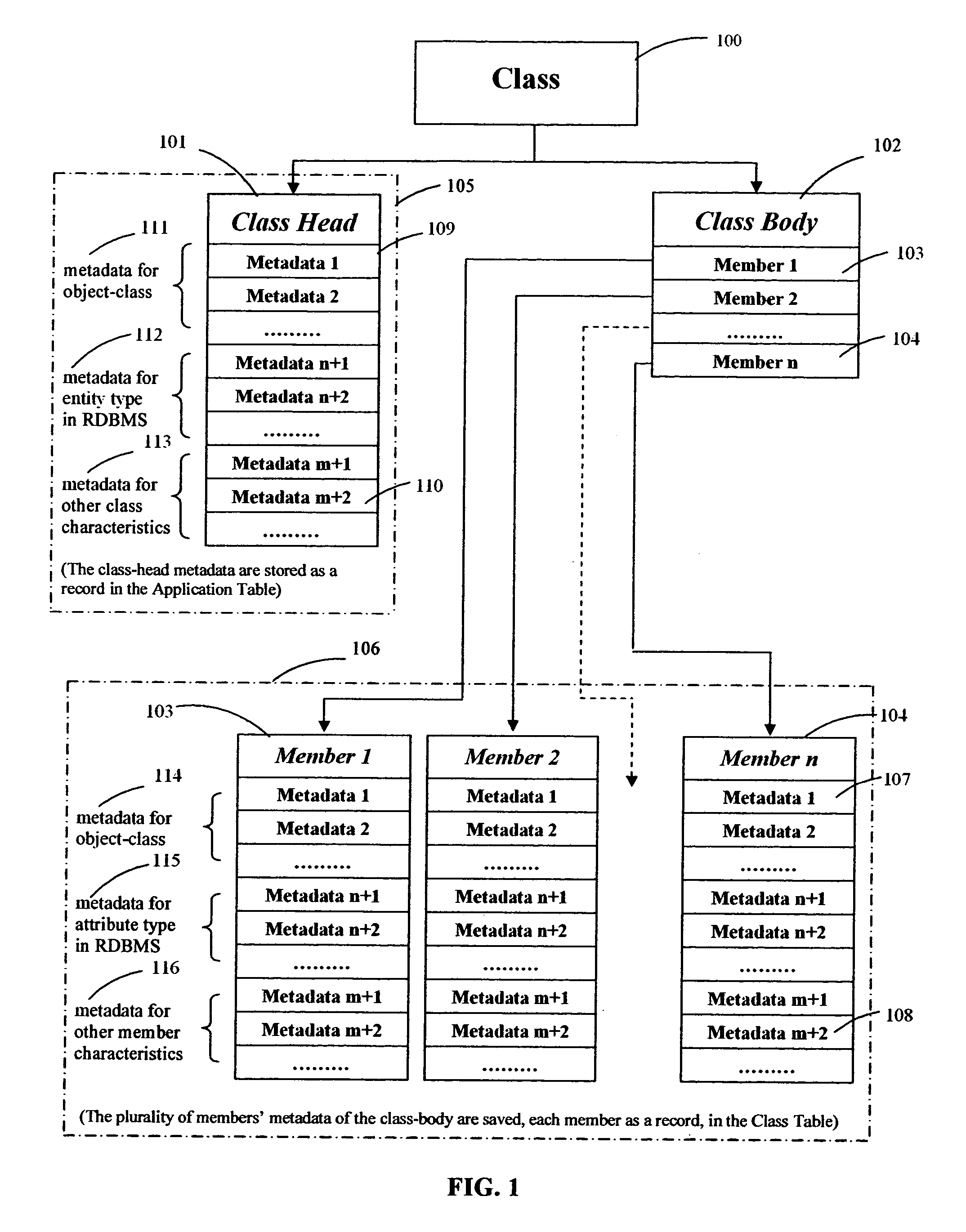
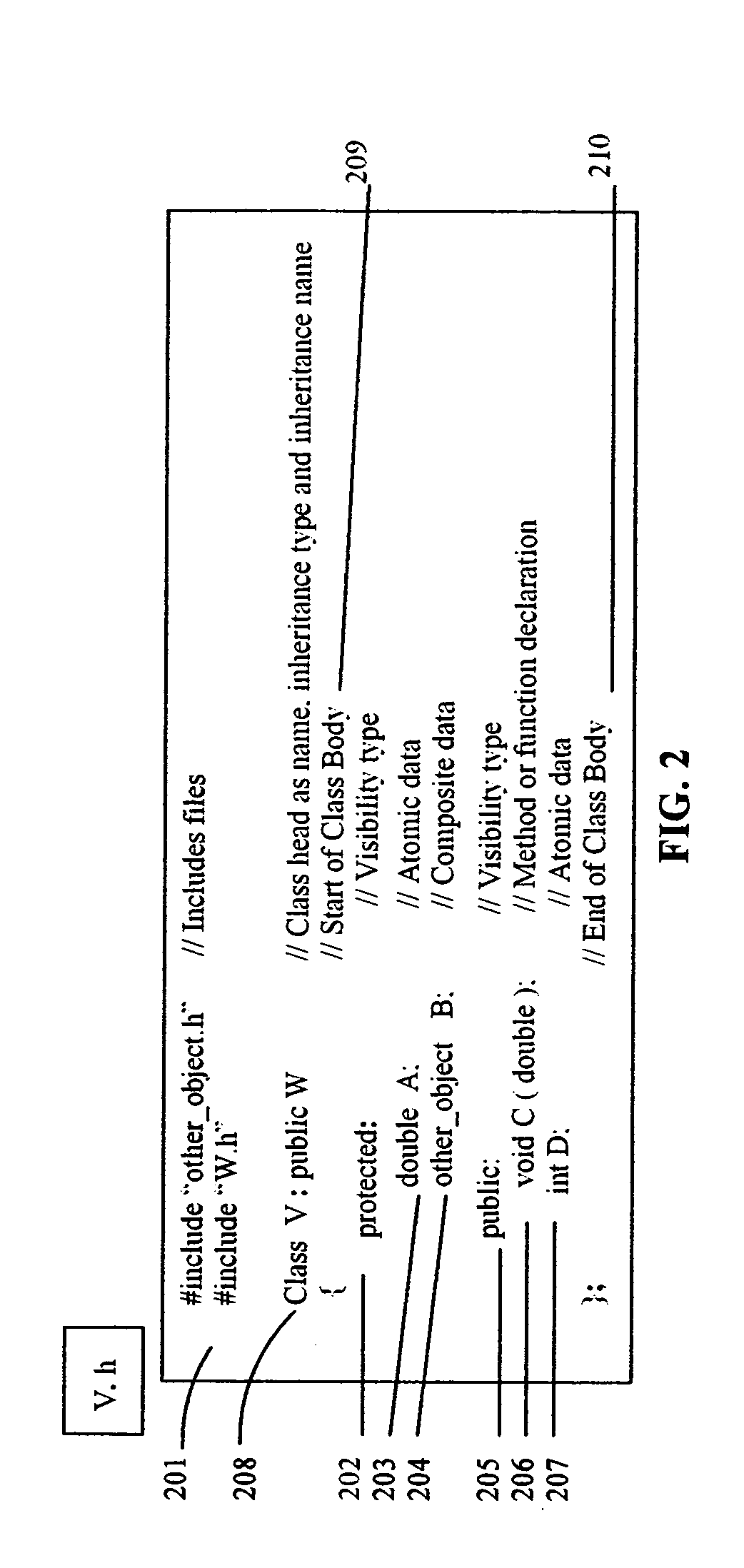
[0072]A class is a description tool used in a program to define a set of attributes and a set of methods that characterize the members of an object. The definition of classes in OOPL is comparable to the definition of types in languages such as C or Pascal. For example, in C++ a class is defined as a structure that contains data elements as well as functions that manipulate these data elements.

[0073]The benefits of an object-oriented approach arise out of three basic principles: encapsulation, polymorphism and inheritance. Generally speaking, from a programming point of view, an object model is a unifying set of rules that describe object structure, object lifecycle, and inter-object communication. Object structure relates to the physical layout of objects in memory. Object lifecycle refers to how applications create and destroy objects. Inter-object communication refers to protocols by which objects communicate with one another. Most OOPLs do not specify true object models,...


PUM


Abstract

The invention relates to a method for enhancing an object-oriented programming language. The method includes declaring one or more class structures in databases having metadata describing characteristics defining the class structures. The method also includes extending the metadata associated with the class structures by adding any number of additional metadata to the databases.

Description

CROSS-REFERENCE TO RELATED APPLICATIONS[0001]This application claims the benefit of U.S. Provisional Application No. 60 / 505,908, entitled “Direct deployment of an object-oriented application written as a set of relational database tables,” filed Sep. 24, 2003. The provisional application Ser. No. 60 / 505,908 is incorporated by reference herein.TECHNICAL FIELD[0002]The present invention relates to an object-oriented programming environment that uses relational database management system techniques for the software development.BACKGROUND[0003]Innovation in the modern business world is often an unquenchable necessity which demands more from, and imposes more complexity upon, software. Conventional software development is itself frequently a complex process typically consisting of authoring source code using a particular programming language. Most modern-day software applications are created using a high level object-oriented programming language (“OOPL”) such as C++, Smalltalk, or Java®...

Claims


Application Information

Patent Timeline
Patent Type & Authority Patents(United States)
IPC IPC(8): G06F17/30G06F9/44G06F17/20G06FG06F7/00G06F17/00G06F40/00
CPCG06F8/24G06F8/34Y10S707/99943Y10S707/99944
Inventor DIAB, SALLEH
Owner CALLAHAN CELLULAR L L C
Why Eureka
Try Eureka