Spin stand testing system with fine positioner for head stack assembly

Active Publication Date: 2006-11-07
WESTERN DIGITAL TECH INC
View PDF32 Cites 170 Cited by
  • Summary
  • Abstract
  • Description
  • Claims
  • Application Information

AI Technical Summary

Benefits of technology

[0010]In some embodiments, the fine positioner further includes an actuator housing having a shape of a parallelogram. In some of these embodiments, the piezoelectric actuator is disposed within the parallelogram. The parallelogram can also include notches that reduce the thickness of the actuator housing near the corners of the parallelogram to deform more easily in response to the piezoelectric actuator. The piezoelectric actuator can deform the parallelogram, in some embodiments, in order to pivot the head stack assembly. In some of these embodiments the fine positioner further includes a set screw disposed against a first end of the piezoelectric actuator, and the piezoelectric actuator works against the set screw to deform the parallelogram. The set screw can also provide a pre-load to the piezoelectric actuator.
[0011]According to an embodiment of the invention, a spin stand testing system comprises a

Problems solved by technology

One issue with spin stand testing relates to the problem of keeping the head aligned with a track on the disk.
However, spin stands historically have been “open-loop” systems, meaning that there is no feedback mechanism for keeping the head aligned with a track.
However, the demand for increased inform

Method used


Image

  • Spin stand testing system with fine positioner for head stack assembly
  • Spin stand testing system with fine positioner for head stack assembly
  • Spin stand testing system with fine positioner for head stack assembly

Examples


Embodiment Construction

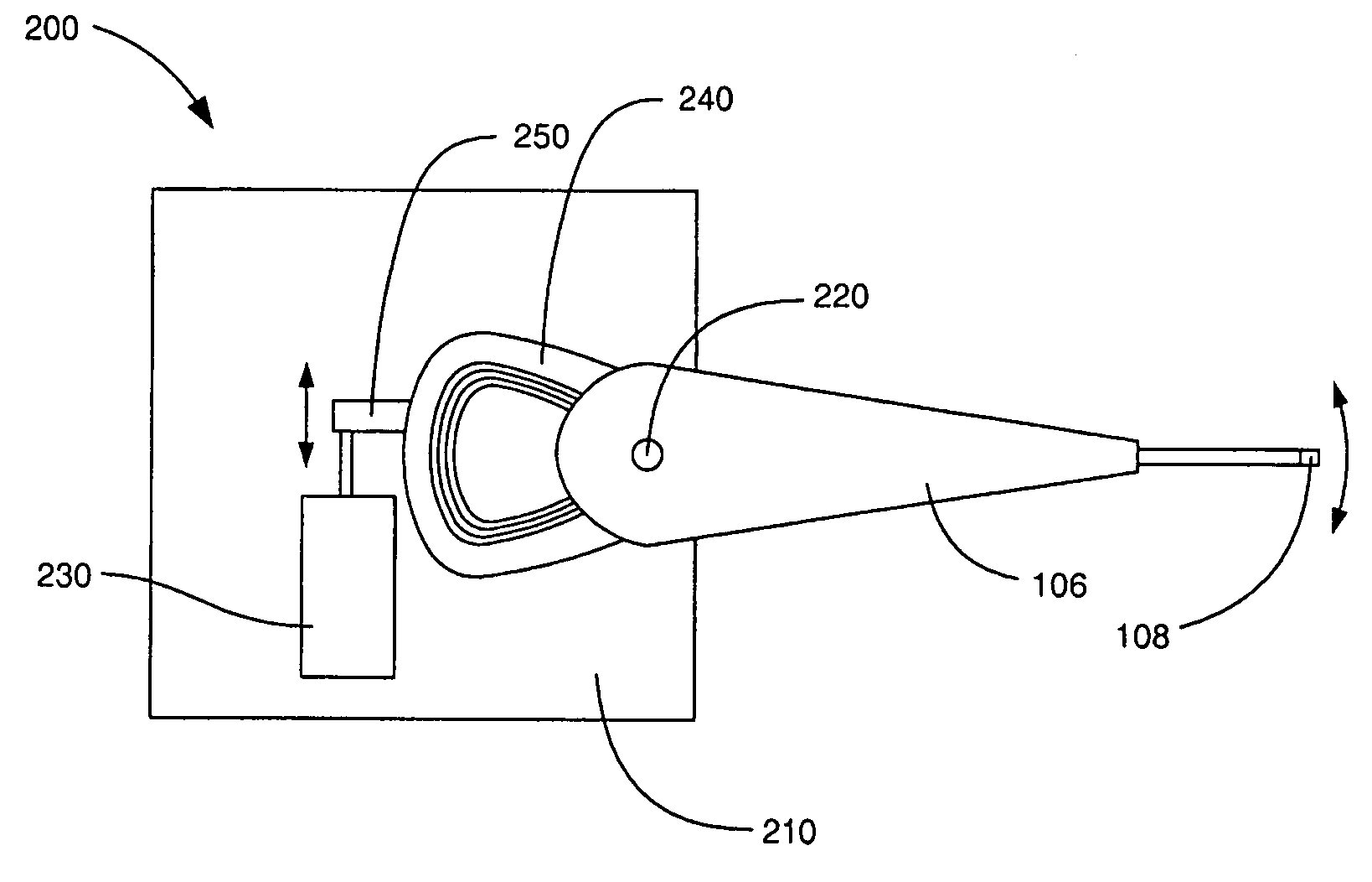
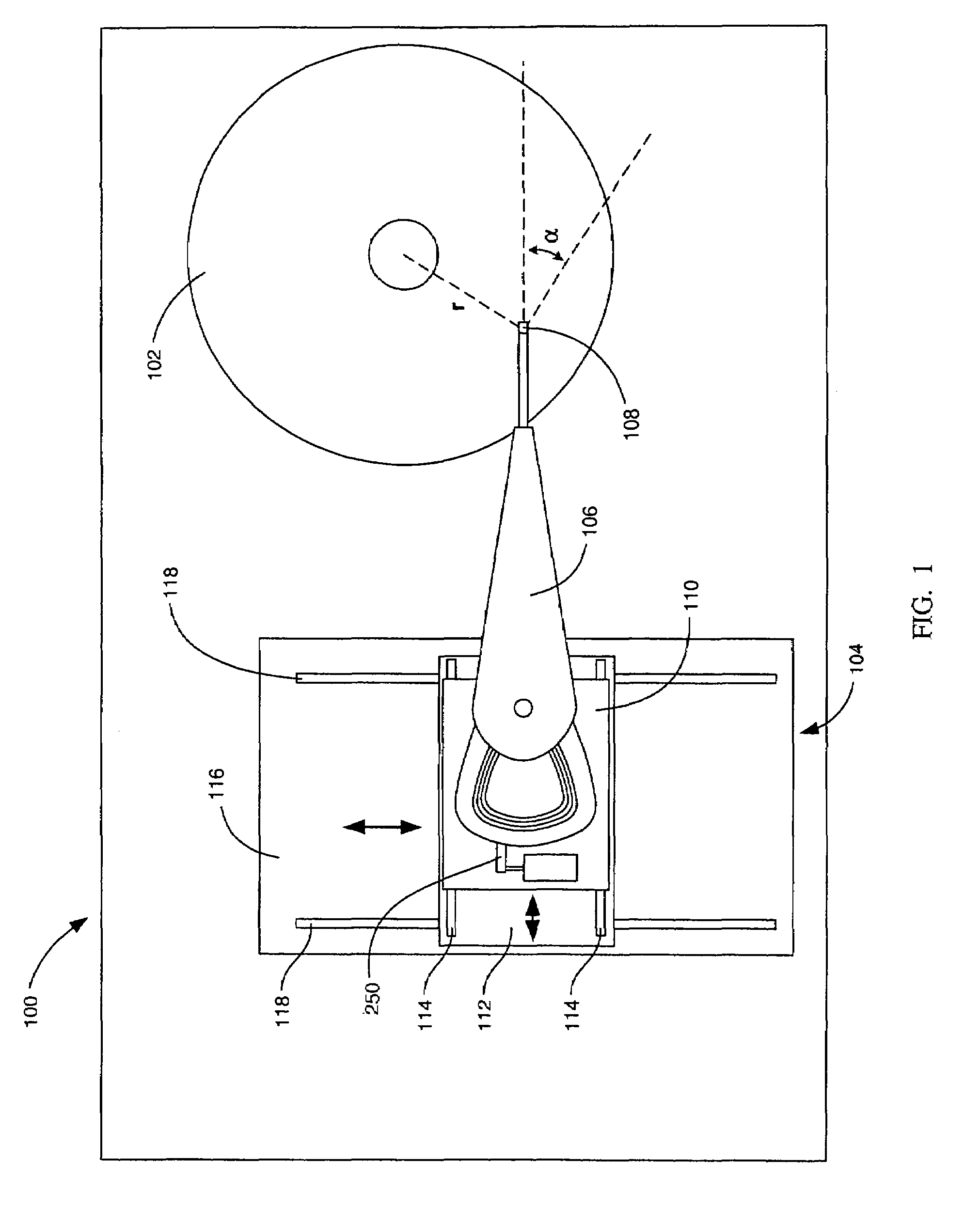
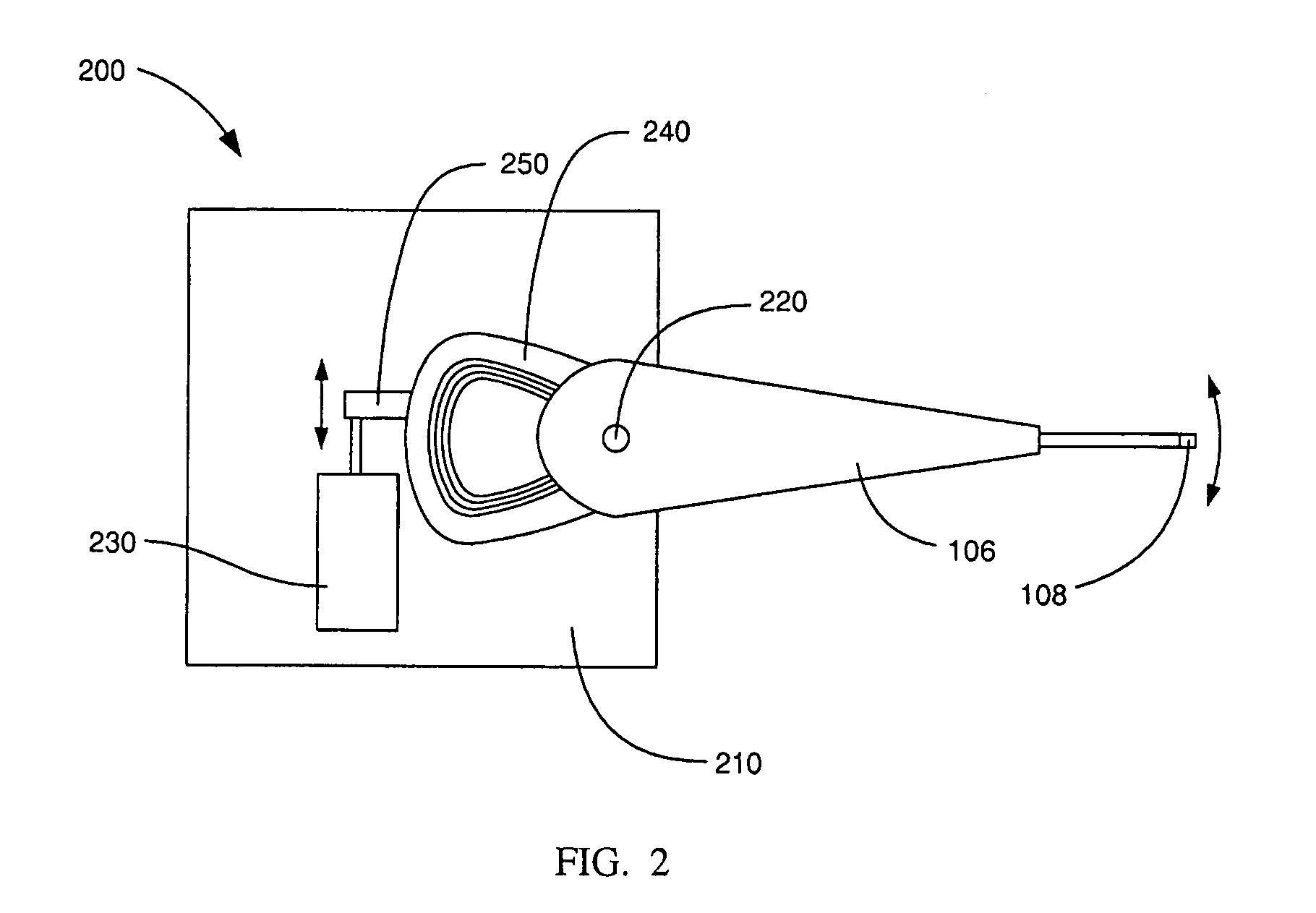
[0016]FIG. 1 is a schematic illustration of an exemplary spin stand testing system 100 according to an embodiment of the invention. The spin stand testing system 100 comprises a disk 102 and a positioning device 104. The disk 102 is representative of a magnetic recording disk that would be used in a disk drive and is configured to rotate around an axis at a variable rotation rate. The positioning device 104 secures a head stack assembly 106, including a head 108, and is configured to position the head 108 to a desired position over the disk 102. The positioning device 104 includes both apparatus for course adjustment and a head stack fixture including a fine positioner for use in a closed-loop servo system as described in more detail with respect to FIGS. 2–5.

[0017]As shown in FIG. 1, the exemplary positioning device 104 comprises an apparatus for course adjustment, which in this example includes two platforms on orthogonal rail systems. More specifically, the head stack assembly 10...


PUM


Abstract

Head stack fixtures for securing head stack assemblies to spin stand testing systems, and spin stand testing systems incorporating such fixtures, are disclosed. Exemplary head stack fixtures comprise a base supporting a piezoelectric actuator. The base includes an attachment mechanism for securing the HSA in such a way that the HSA will pivot relative to the base. When the HSA is secured to the base, the piezoelectric actuator engages the HSA. The piezoelectric actuator is therefore able to pivot the HSA relative to the base for fine positioning of a head of the HSA.

Description

BACKGROUND OF THE INVENTION[0001]1. Field of the Invention[0002]The disclosure relates generally to the field of magnetic disk drives, and more particularly to apparatus and methods related to testing disk drive components.[0003]2. Description of the Prior Art[0004]Magnetic disk drives are used to store and retrieve data for digital electronic apparatuses such as computers. A typical magnetic disk drive comprises a head, including a slider and a transducer, in very close proximity to a surface of a rotatable magnetic disk. The transducer, in turn, includes a write element and / or a read element. As the magnetic disk rotates beneath the head, a very thin air bearing is formed between the surface of the magnetic disk and an air bearing surface of the slider. The air bearing causes the head to “fly” above the surface of the magnetic disk with a separation (“fly height”) that is typically less than 40 nanometers in contemporary disk drives. As the head flies over the magnetic disk, the w...

Claims


Application Information

Patent Timeline
IPC IPC(8): G11B5/56G01R33/12
CPCG11B5/455G11B5/4555G11B27/36G11B5/5552
Inventor BUTTAR, JAGDEEP S.TERRILL, DAVIDDAVIES, KENNETH R.FERRIER, HERMANCHE, XIAODONG
Owner WESTERN DIGITAL TECH INC
Why Eureka
Try Eureka