Landscape edging form assembly and method

a technology for landscape edging and form assembly, which is applied in the field of concrete landscape edging, can solve the problems of inability to meet the needs of a home handyman, a small contractor, a large contractor, and a small contractor, and achieves the effect of convenient use, easy and quick erection and lay

Inactive Publication Date: 2006-11-07
BOGRETT BLAKE B
View PDF55 Cites 15 Cited by
  • Summary
  • Abstract
  • Description
  • Claims
  • Application Information

AI Technical Summary

Benefits of technology

[0012]The in place landscape edging formation system and method of the subject invention for making concrete landscape edging provide an easy to use, inexpensive system and method for making concrete landscape edging. The landscape edging form assemblies of the subject invention are inexpensive; can be made of disposable or reusable materials; can be easily and quickly erected and laid down in straight, angled, curved, sinuous, circular, or oval configurations at the job site by either unskilled or skilled labor; and preferably, are prefabricated.
[0014]A second landscape edging form assembly of the subject invention includes two sidewalls that are rigid, flexible, or bendable and made of an inexpensive material, e.g. corrugated board such as but not limited to a corrugated paperboard. One of the sidewalls of this landscape edging form assembly has an upper section and a lower section. The lower section of this sidewall is spaced laterally outward from the upper section along the length of this second form assembly. Preferably, the sidewalls of this landscape edging form assembly are interconnected by a series of flexible connectors (e.g. flexible connectors such as strands, wires, straps, strings, cords or twines that are made from organic or inorganic fibers or filaments). As with the first landscape edging form assembly of the subject invention, the lengths of the flexible connectors of this second form assembly are selected relative to each to locate the sidewalls of the form assembly a selected distance apart along the length of the form assembly. With this structure, when the form assembly is erected at the job site, the sidewalls of the form assembly are located to provide the landscape edging form assembly and the concrete landscape edging formed with the form assembly with the desired width and contours along its length. The stepped concrete landscape edging made with this second form not only is aesthetically pleasing, but also permits the wheels of a lawnmower to run along the concrete landscape edging to easily cut the grass right up to the edging.
[0015]The flexible connectors interconnecting the sidewalls of the first two embodiments of the landscape edging form assembly of the invention are inexpensive. In addition, the use of the flexible connectors in these embodiments of the landscape edging form assembly of the subject invention enables the landscape edging form assembly of the subject invention to be prefabricated; easily packaged in a collapsed and compact configuration for storage, shipment, and handling; and quickly and easily unpackaged and erected at the job site. Typically, the landscape edging form assemblies of the subject invention utilize spacers that enable the form assemblies to be accurately and quickly set up with the sidewalls of the form assemblies held in place at the selected spacing(s). In some embodiments of the invention, the spacers also form control joints at spaced apart locations along the length of concrete landscape edgings formed with the form assemblies. The spacers can be made of various materials, e.g. polymeric sheet materials, foamed polymeric based sheet materials, metal, wood, corrugated board, etc. and can be disposable or reusable.
[0017]The interior surfaces of the sidewalls of the forms of the subject invention can be treated with a release agent, can be embossed or debossed to create an aesthetic design, effect, or pattern in the concrete, and / or can have a colorant that transfers to the concrete. In addition, the upper edges of the sidewalls, especially when the sidewalls are made of corrugated paperboard, can be sealed to prevent moisture from entering the walls through their upper edges when the forms are filled with concrete. One embodiment of the landscape edging form of the subject invention includes the ability to adjust the flexible connectors relative to the sidewalls of the form at the job site to shape the form into various selected curvatures. In another embodiment of the invention, the landscape edging form of the subject invention is prefabricated with the flexible connectors connecting the sidewalls of the form locating the sidewalls with a preselected round, oval, or sinuous curvature.
[0018]As used herein, the term “Portland cement” refers to a powder of alumina, silica, lime, iron oxide and magnesium oxide used as an ingredient of concrete. As used herein the term “concrete” means a building material made by mixing a cementing material (e.g. portland cement) and a mineral aggregate (as sand and gravel) with sufficient water to cause the cement to set and bind the entire mass or a building material (mortar) made by mixing a cementing material (e.g. portland cement) and a mineral aggregate (as sand) with sufficient water to cause the cement to set and bind the entire mass.

Problems solved by technology

While a concrete edging extrusion machine can be used to form a continuous concrete edging, with the expense, expertise, and labor required in connection with the use of a concrete edging extrusion machine, such a machine is not a practical option for a home handy-man, a small contractor, or even a large contractor when the edging job to be performed is a relatively small job, such as the concrete landscape edging requirements for a home owner.
Reusable forming systems, such as those made of steel and commonly used for large commercial applications, are also too expensive and cumbersome to transport, handle, and set up for a home handy-man, a small contractor or even a large contractor when the edging job to be performed is a relatively small job, such as the concrete landscape edging requirements for a home owner.
However, there are several problems inherent in the building of landscape edging forms from existing building materials for the in place formation of concrete landscape edging.
In addition to the expense, dimensional lumber is relatively bulky, heavy, and increasingly not very straight.
These stakes are typically heavy, bulky, and expensive and can be easily misaligned so that the dimensional lumber sidewalls of the form(s) are not parallel with respect to each other.
In addition, it is very common for the sidewalls in this type of landscape edging form to shift prior to or during the introduction and working of the concrete within the form so that a finished concrete landscape edging made with the form is not uniform in width.
The release agent may be an oil-based product and, like many of the other fabrication steps required in the construction of these wooden edging forms, the application of the release agent to the wooden forms by hand brushing or spraying is labor intensive and time consuming.
In addition, the application of the release agent to the wooden forms at the job site typically results in some ground contamination.
In addition to the time, work, expense, and expertise required to fabricate landscape edging forms from dimensional lumber, the use of such forms often presents disposal problems.
However, the dimensional lumber of these wooden forms is typically covered with a thin layer of hardened concrete.
Disposing of lengths of dimensional lumber covered with concrete and a release agent can be expensive and / or labor intensive.
Another drawback to using dimensional lumber for the fabrication of landscape edging forms is that dimensional lumber landscape edging forms are best suited for the creation of straight sections of concrete landscape edging.
For many applications where a circular or smooth curved section of concrete landscape edging is desired, it is not practical for a home-handyman or small contractor (due to a lack of skill and / or time) to construct a landscape edging form from dimensional lumber that can be used to make such a circular or smooth curved section of concrete landscape edging.

Method used


Image

  • Landscape edging form assembly and method
  • Landscape edging form assembly and method
  • Landscape edging form assembly and method

Examples


Embodiment Construction

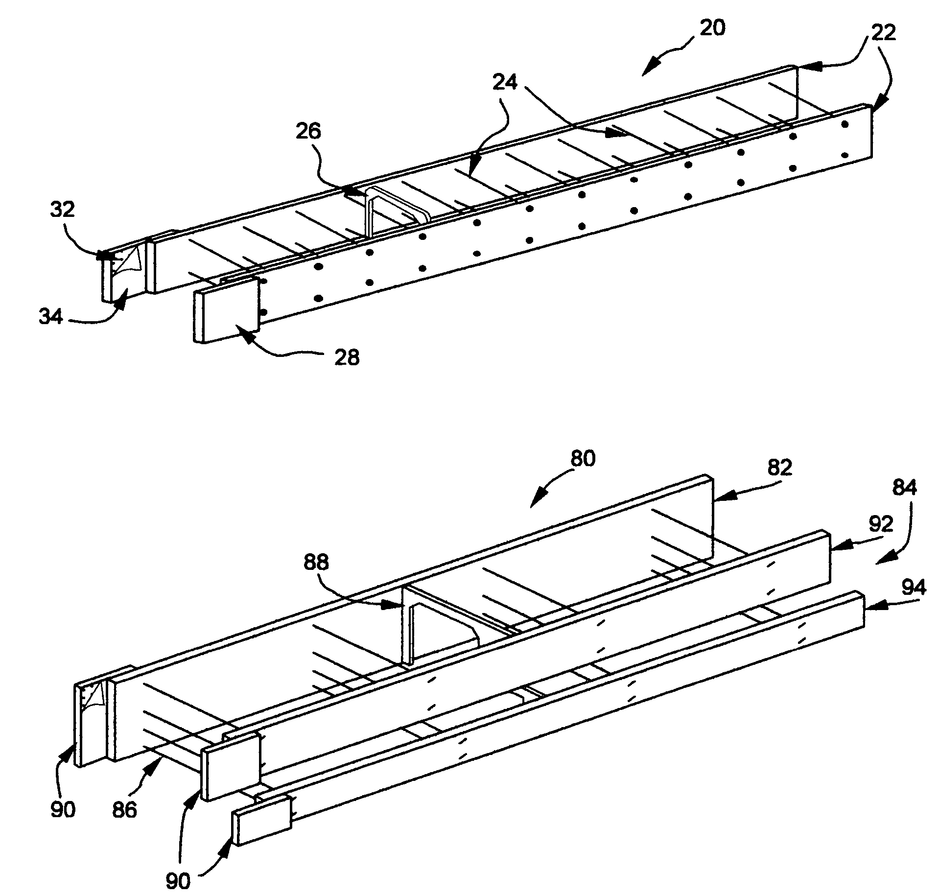
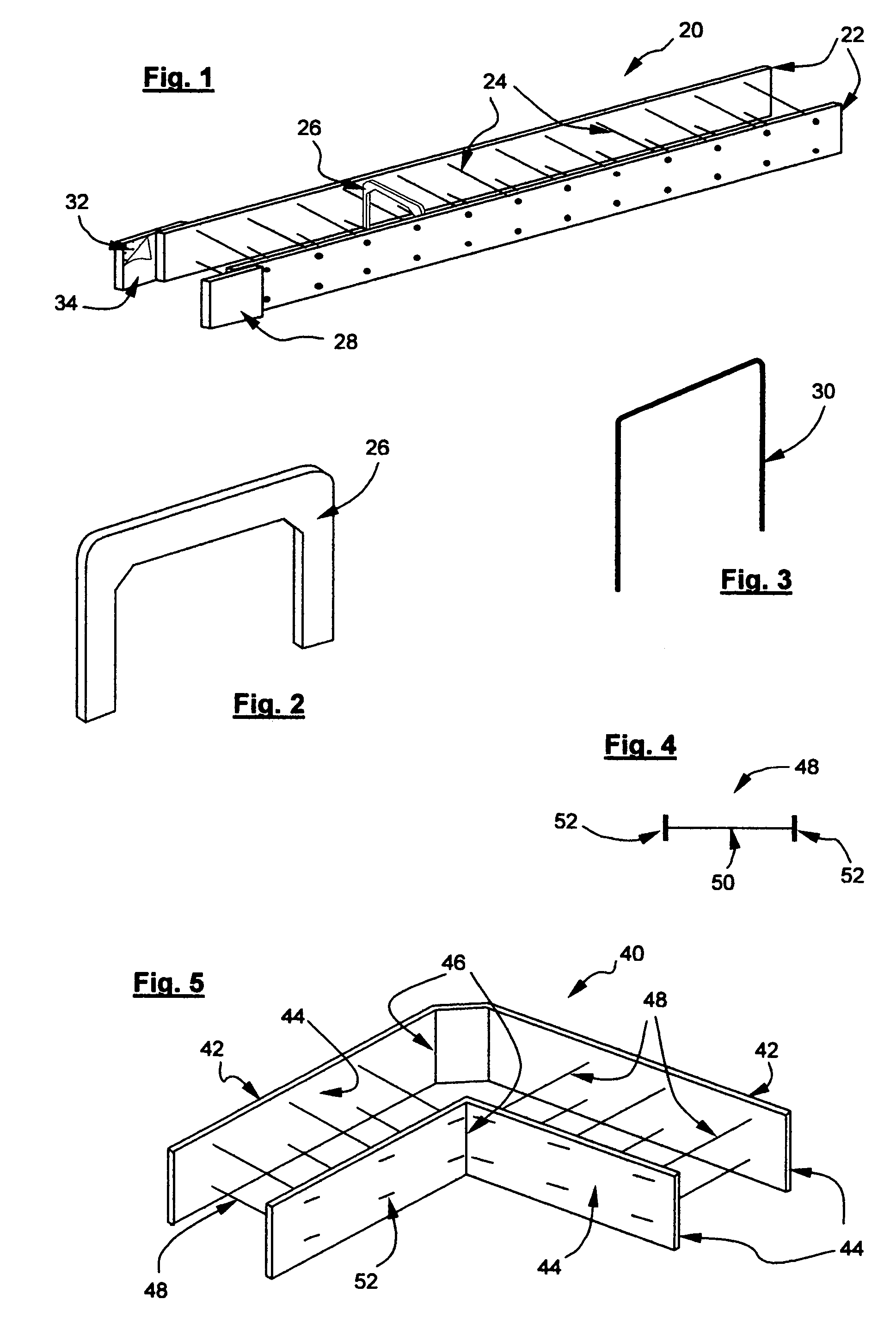
[0040]FIG. 1 is a schematic perspective view showing a landscape edging form assembly 20 of the subject invention that is designed to form straight lengths of concrete landscape edging in place. The landscape edging form assembly as shown in FIG. 1 is erected and includes first and second sidewalls 22, flexible connector strands 24, one or more spacers 26, and joining extensions 28 for joining the landscape edging form assembly 20 with an adjacent landscape edging form assembly in the fabrication of a landscape edging form made up of a plurality of the landscape edging form assemblies 20. While the landscape edging form assembly 20 is typically about 2 to about 8 inches wide, by about 3 to about 8 inches high, by about 4 to about 10 feet in length, the width, height, and length of the landscape edging form assembly 20 can be selected to best fulfill the requirements of a particular application.

[0041]The first and second sidewalls 22 of the landscape edging form assembly 20 may be ma...


PUM


Abstract

A landscape edging form assembly for forming a concrete edging in place, includes first and second sidewalls and a series of flexible connectors extending between and interconnecting the sidewalls. The flexible connectors are spaced apart from each other in the direction of the length of the landscape edging form and enable the landscape edging form to be extended from a non-erected width where the flexible connectors are in a slack condition to an erected width where the flexible connectors are in a taut condition. Preferably, the sidewalls and the interconnecting flexible connectors of the landscape edging form assembly are a prefabricated component of the assembly. Another form assembly includes bendable sidewalls, spacers, and positioning brackets and is used to form a sinuous concrete landscape edging in place.

Description

BACKGROUND OF THE INVENTION[0001]The subject invention relates to concrete landscape edging and in particular to an easy to use, inexpensive, landscape edging form assembly and method of utilizing the landscape edging form assembly to construct concrete landscape edging in place. While the landscape edging form assembly of the subject invention is particularly well suited for use in making concrete landscape edging such as but not limited to concrete edging bordering a garden or lawn, surrounding a tree, plants, or shrubbery, or adjacent a walkway, a driveway, it should be understood that the landscape edging form assembly of the subject invention may also be used to make other concrete edgings associated with landscaping such as but not limited to the edging for a patio or deck, the edging surrounding a swimming pool deck, sandbox or play area, retaining walls, and other applications where an elongated concrete structure having a transverse cross section up to about two feet wide i...

Claims


Application Information

Patent Timeline
Patent Type & Authority Patents(United States)
IPC IPC(8): E04G9/08
CPCA01G1/08E04B2/8647E04B2002/867A01G9/28
Inventor BOGRETT, BLAKE B.
Owner BOGRETT BLAKE B
Why Eureka
Try Eureka