
Plasma arc torch electrode

a plasma arc torch and electrode technology, applied in the field of plasma arc torch electrodes, can solve the problems of time-consuming and cumbersome replacement of consumable components, limited cooling fluid flow in plasma arc torch known art, and inability to accurately measure the temperature of the plasma arc torch, etc., to achieve efficient attachment and improve cooling

Inactive Publication Date: 2006-11-07
VICTOR EQUIP
View PDF6 Cites 25 Cited by
  • Summary
  • Abstract
  • Description
  • Claims
  • Application Information

AI Technical Summary

Benefits of technology

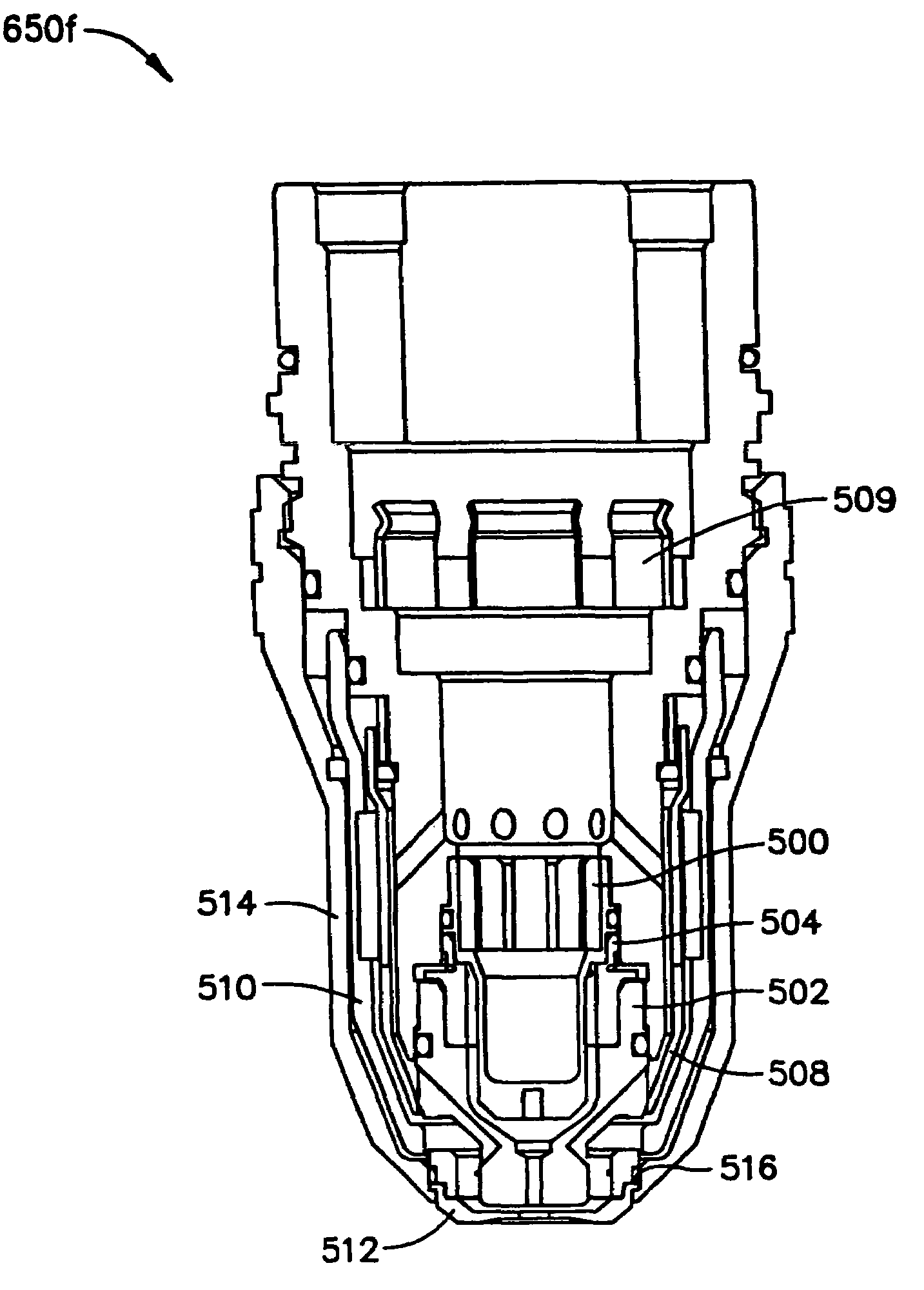
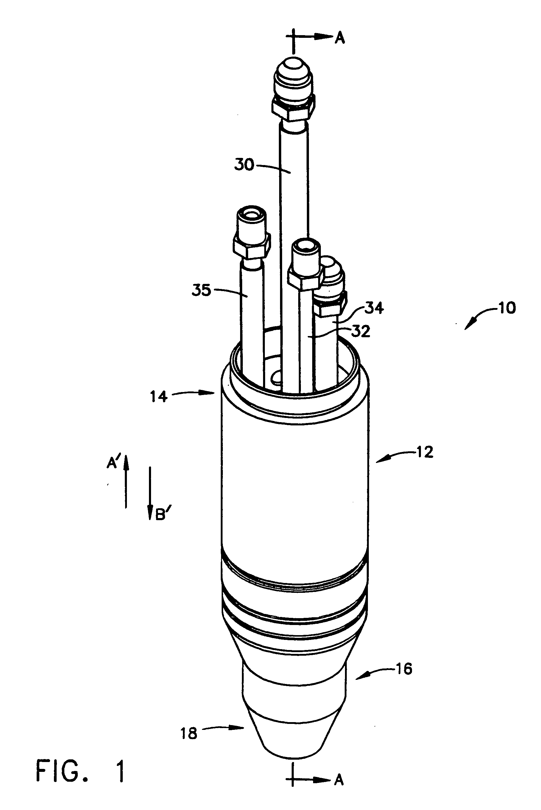
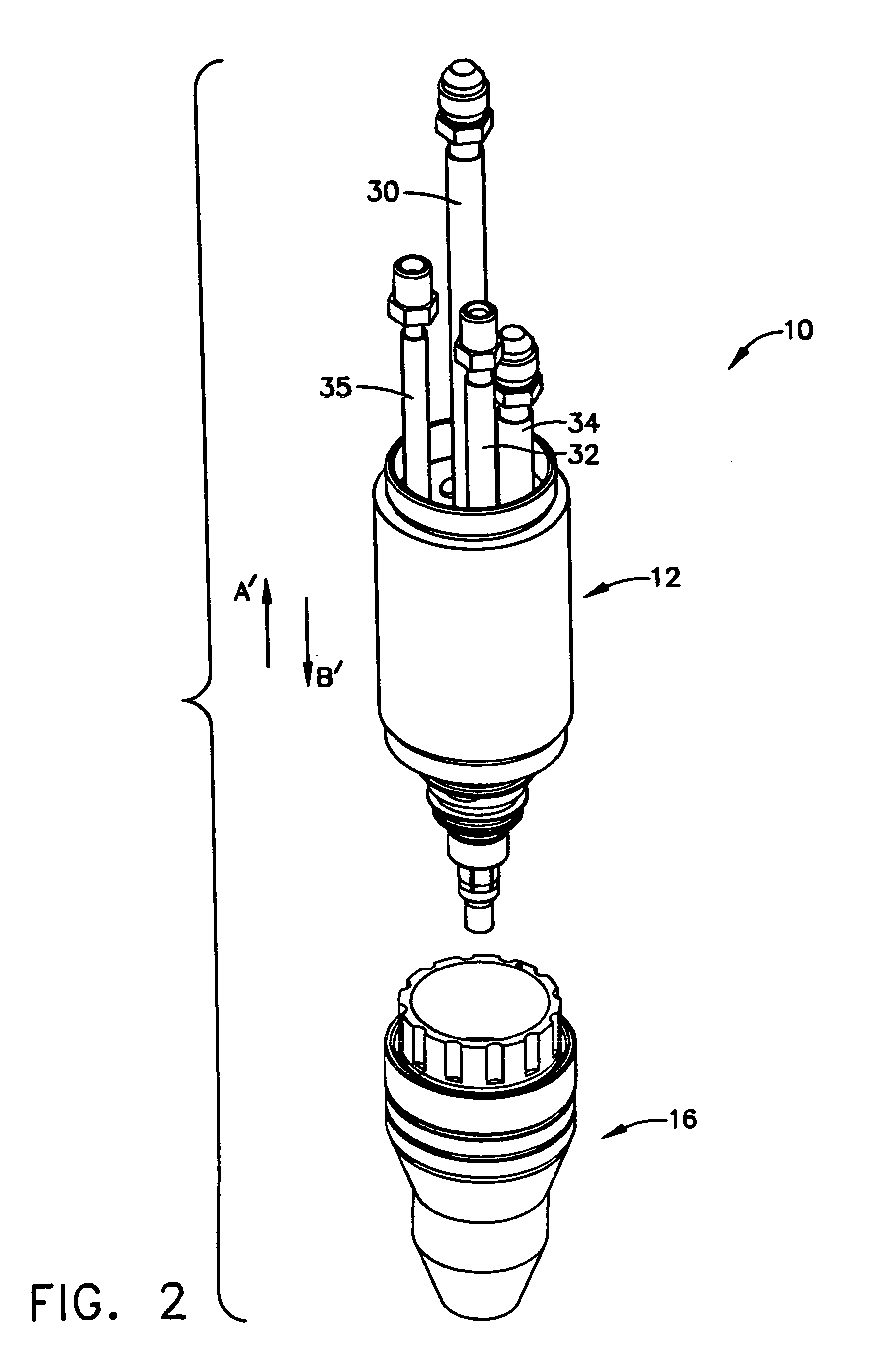
[0010]In another form of the present invention, the consumable components further comprise a coolant seal and guide disposed between the tip and the secondary cap to direct and control the flow of cooling fluid. The electrode is centrally disposed within the cartridge body and is in electrical contact with the cathode along an interior portion of the electrode. The electrode and cathode are configured such that a passageway is formed therebetween for the passage of a cooling fluid proximate, or through an adjacent vicinity of, the electrical contact. The electrode further defines a central cavity that is in fluid communication with the coolant tube such that the cathode and electrode, along with other torch components, are properly cooled during operation. Further, the cartridge body generally distributes cooling fluid, plasma gas, and secondary gas, while providing separation or dielectric between various torch components as described in the detailed description that follows. Moreover, the fluid (cooling, plasma, secondary) is distributed in a coaxial flow between various torch components, which increases the total amount of flow and cooling within the plasma arc torch.
[0013]In other forms, several electrode and tip configurations are provided that improve cooling, provide electrical continuity through the cathode and anode side of the power supply, respectively, and that provide efficient attachment of the electrode and tip to the plasma arc torch. Additionally, configurations for consumable cartridges are provided, wherein a single cartridge containing one or more consumable components is removed and replaced when the one or more consumable components require replacement, rather than replacing individual consumable components one at a time. Moreover, configurations for securing the torch head to adjacent components such as a positioning tube are also provided by other forms of the present invention.

Problems solved by technology

However, the flow of cooling fluids in plasma arc torches of the known art have been relatively limited due to the positioning and configuration of internal cooling passageways.
Further, the electrode and the tip are commonly known as consumable components, which must replaced after a certain period of operation due to wear and / or damage that occurs during operation.
Additionally, when the consumable components are replaced, tools are often required for removal due to the type of connection between the consumable components and a torch head.
As a result, the replacement of consumable components is often time consuming and cumbersome for a plasma arc torch operator.
Moreover, each of the consumable components are typically replaced on an individual basis, rather than all at once, thereby making removal and installation of several different consumable components at different even more time consuming and cumbersome.

Method used


Image

  • Plasma arc torch electrode
  • Plasma arc torch electrode
  • Plasma arc torch electrode

Examples


first embodiment

[0132]In a first embodiment as shown in FIGS. 12a through 12d, the electrode 100a defines flutes 220 and raised ribs 222. The flutes 220 form a fluid passageway between the electrode 100a and the cathode 22a (best shown in FIG. 12d) for cooling proximate the electrical contact between the electrode 100a and the cathode 22a. More specifically, the flutes 220 produce a relatively high velocity flow proximate the interface between the electrode 100a and the cathode 22a, where cooling is critical. Additionally, the raised ribs 222 are in electrical contact with an outer wall 224 of the cathode 22a, which provides electrical continuity between the cathodic members (i.e. cathode, electrode) of the plasma arc torch 10. Preferably, the outer wall 224 defines a plurality of axial tabs 226 as shown in FIG. 12b such that the cathode cap 40 and the coolant tube 42 may be more easily assembled within the cathode 22a.

[0133]Referring specifically to FIG. 12d, which is a view showing the lateral i...

second embodiment

[0134]As shown in FIGS. 13a through 13c, the electrode indicated as 100b may alternately define axial passageways 230 rather than the flutes 220, wherein the axial passageways 230 produce the relatively high velocity flow of the cooling fluid that flows proximally therethrough. Accordingly, the cooling fluid flows proximally through the axial passageways 230 to cool the interface between the electrode 100b and the cathode 22b. For electrical contact, an internal wall 228 is formed within the electrode 100b that makes contact with the outer wall 224 of the cathode 22b.

[0135]Referring to FIG. 13c, which is a lateral view through the interface between the electrode 100b and the cathode 22b, the electrode 100b defines a perimeter surface 229 and the cathode 22b defines a perimeter surface 331. Accordingly, the perimeter surface 229 of the electrode 100b is adjacent the perimeter surface 331 of the cathode 22b. (The surfaces are shown in FIG. 13c with a slight gap for illustration purpo...

third embodiment

[0136]In the electrode indicated as 100c in FIGS. 14a and 14b, the electrode 100c defines radial passageways 232 and axial slots 234 to provide cooling between the electrode 100c and the cathode 22c. The cooling fluid generally flows proximally to the radial passageways 232 and then proximally to the axial slots 234, wherein the cooling fluid exits the interface between the electrode 100c and the cathode 22c and proceeds through the passageways 130 as previously described. For electrical contact, an internal wall 236 is similarly formed within the electrode 100c that makes contact with the outer wall 224 of the cathode 22c. Accordingly, a perimeter surface of the electrode 100c is adjacent a perimeter surface of the cathode 22c to form a fluid passageway for cooling proximate the electrical contact.


PUM

PropertyMeasurementUnit
temperaturesaaaaaaaaaa
perimeteraaaaaaaaaa

Abstract

A variety of electrodes for use in a plasma arc torch are provided that improve cooling between the electrode and an adjacent cathodic element such as a cathode. At least one passageway is formed between the electrode and the cathode for the flow of a fluid, e.g. cooling fluid, wherein the flow of the fluid is proximate, or through an adjacent vicinity of, electrical contact between the cathode and the electrode. The passageway is formed through the electrode, through the cathode, between the electrode and the cathode, and through a third element in the various forms of the present invention. Further, methods of operating a plasma arc torch using the electrodes according to the various forms of the invention are also provided.

Description

CROSS-REFERENCE TO RELATED APPLICATIONS [0001]This application is a continuation in part of U.S. patent application Ser. No. 10 / 409,633 entitled “Plasma Arc Torch Electrode,” filed 7 Apr. 2003, the contents of which are incorporated herein by reference in their entirety and continued preservation of which is requested.FIELD OF THE INVENTION [0002]The present invention relates generally to plasma arc torches and more particularly to electrodes and methods of use for automated, high current plasma arc torches.BACKGROUND OF THE INVENTION [0003]Plasma arc torches, also known as electric arc torches, are commonly used for cutting, marking, gouging, and welding metal workpieces by directing a high energy plasma stream consisting of ionized gas particles toward the workpiece. In a typical plasma arc torch, the gas to be ionized is supplied to a distal end of the torch and flows past an electrode before exiting through an orifice in the tip, or nozzle, of the plasma arc torch. The electrode...

Claims


Application Information

Patent Timeline
Patent Type & Authority Patents(United States)
IPC IPC(8): B23K10/00H05H1/34
CPCH05H1/34H05H2001/3436H05H2001/3442H05H2001/3489H05H1/3436H05H1/3442H05H1/3489
Inventor CONWAY, CHRISTOPHER J.MACKENZIE, DARRIN H.KELKAR, MILIND G.PUTNAM, GEOFFERY H.
Owner VICTOR EQUIP
Learn More