

Bobbin, motor, and method of winding magnet wire
a technology of magnet wire and winding rod, which is applied in the direction of windings, magnetic circuit rotating parts, magnetic circuit shape/form/construction, etc., can solve the problems of reducing protection reliability, affecting the protection effect, so as to achieve the effect of variable tension
- Summary
- Abstract
- Description
- Claims
- Application Information
AI Technical Summary
Benefits of technology
Problems solved by technology
Method used
Image

Examples
first embodiment
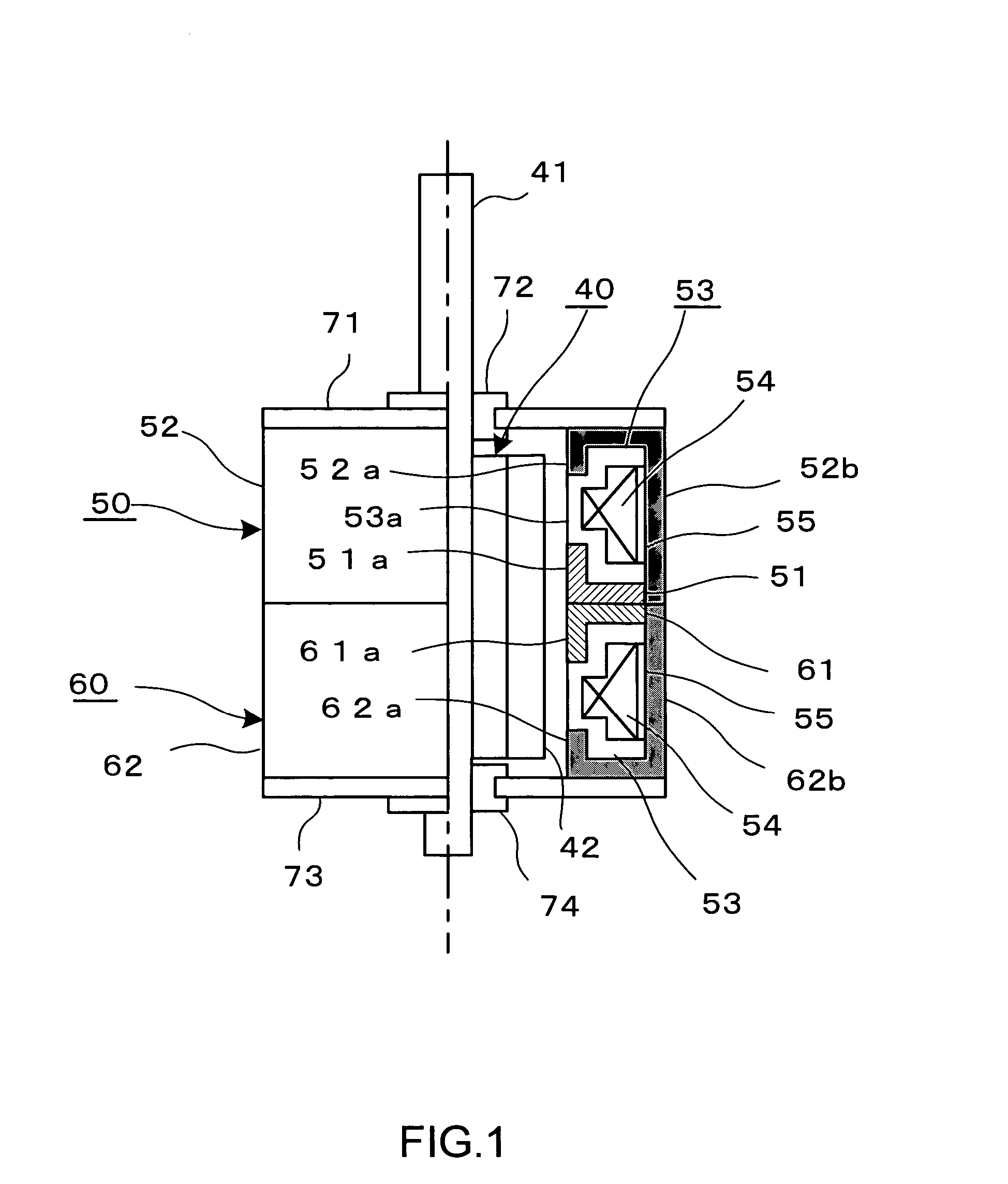
[0028]the present invention will be described with reference to FIGS. 1 and 2.
[0029]A stepping motor shown in FIG. 1 is capable of two-phase driving, and comprises a rotor assembly 40, and two stator units 50 and 60.
[0030]The rotor assembly 10 is shaped substantially cylindrical, and is composed of a permanent magnet with a plurality of magnetic poles 42, and a rotary shaft 41 passing through the center of the magnet.
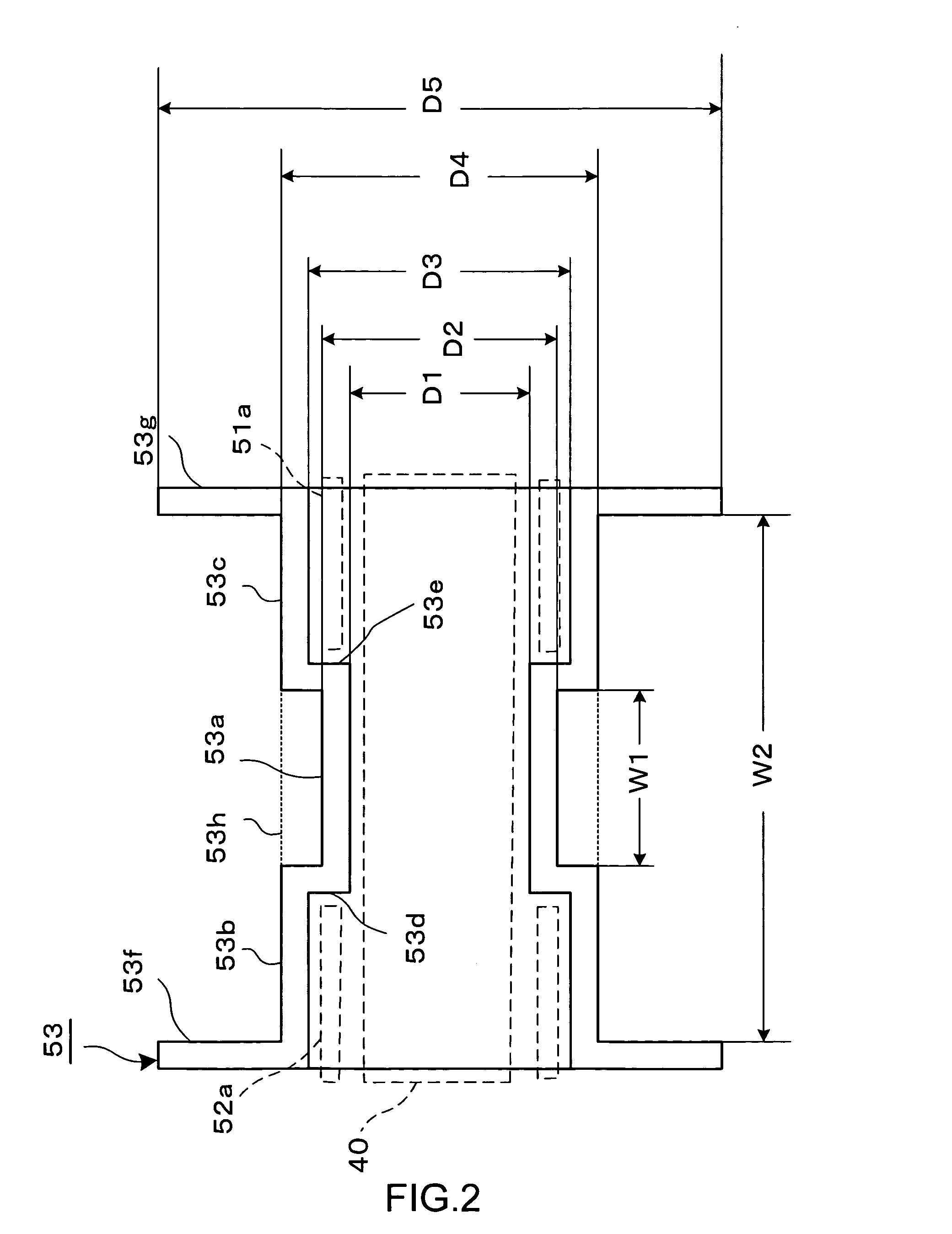
[0031]The stator unit 50 includes first and second yokes 51 and 52 arranged to oppose each other, and a bobbin 53. The bobbin 53 has a magnet wire 54 wound therearound, and an insulator 55 is disposed around the magnet wire 54 wound. The bobbin 53 is sandwiched between the first and second yokes 51 and 52.
[0032]The first yoke 51 is punched out of a soft-magnetic plate into a disk having at its center a circular opening for letting the rotor assembly 40 through. A plurality of pole teeth 51a are formed along an inner circumference of the first yoke 51 defined by the circ...
second embodiment
[0056]the present invention will be described with reference to FIG. 3.
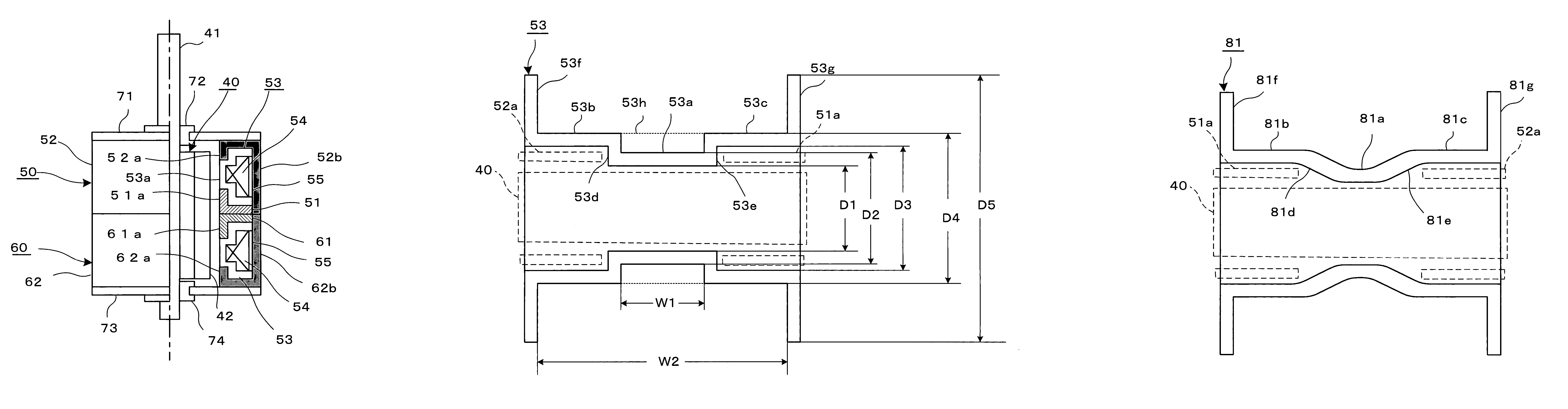
[0057]A bobbin 81 shown in FIG. 3 is formed of synthetic resin, and comprises a middle body section 81a shaped hollow-cylindrical, and two lateral body sections 81b and 81c shaped hollow-cylindrical and having a larger diameter than the middle body section 81a. One end of the middle body section 81a is connected to one end of the lateral body section 81b via a joining section 81d with a gradual change in diametrical dimension thus not forming a step configuration, and the other end of the middle body section 81a is connected to one end of the lateral body section 81c via a joining section 81e with a gradual change in diametrical dimension thus not forming a step configuration. The hollows of the middle body section 81a, and the lateral body sections 81b and 81c are set coaxial to one another. A flange 81f is formed at the distal end of the lateral body section 81b so as to radially extend outward, and a flange 81...
third embodiment
[0059]the present invention will be described with reference to FIG. 4. The third embodiment relates to a method for preferably winding a magnet wire around such a bobbin as having a structure described above in the first embodiment, and the description will be made with reference to the bobbin 53.
[0060]Referring to FIG. 4, the bobbin 53 is set on a rotating mechanism 91 of a winding apparatus, and a starting end 54S of the magnet wire 54 is fixed to the flange 53f by a tape (not shown), or the like. The rotating mechanism 91 is such as to rotate the bobbin 53 about its axis. A traverse roll 92 is positioned to the inner face of the flange 53f so that the magnet wire 54 can be wound starting from the distal end of the lateral body section 53b. The traverse roll 92 is made to work in conjunction with the rotating mechanism 91 via a mechanism (not shown) so as to reciprocate the magnet wire 54 in a direction along the axis of the bobbin 53. The winding apparatus has various sensors (n...
PUM
| Property | Measurement | Unit |
|---|---|---|
| circumference | aaaaa | aaaaa |
| diameter | aaaaa | aaaaa |
| length | aaaaa | aaaaa |
Abstract
Description
Claims
Application Information