Image coding apparatus and image coding method
a technology of image coding and coding apparatus, applied in the field of image coding technology, can solve the problems of cpu heavy load, large memory capacity, and large memory capacity required, and achieve the effect of reducing computation time and memory capacity
- Summary
- Abstract
- Description
- Claims
- Application Information
AI Technical Summary
Benefits of technology
Problems solved by technology
Method used
Image

Examples
first embodiment
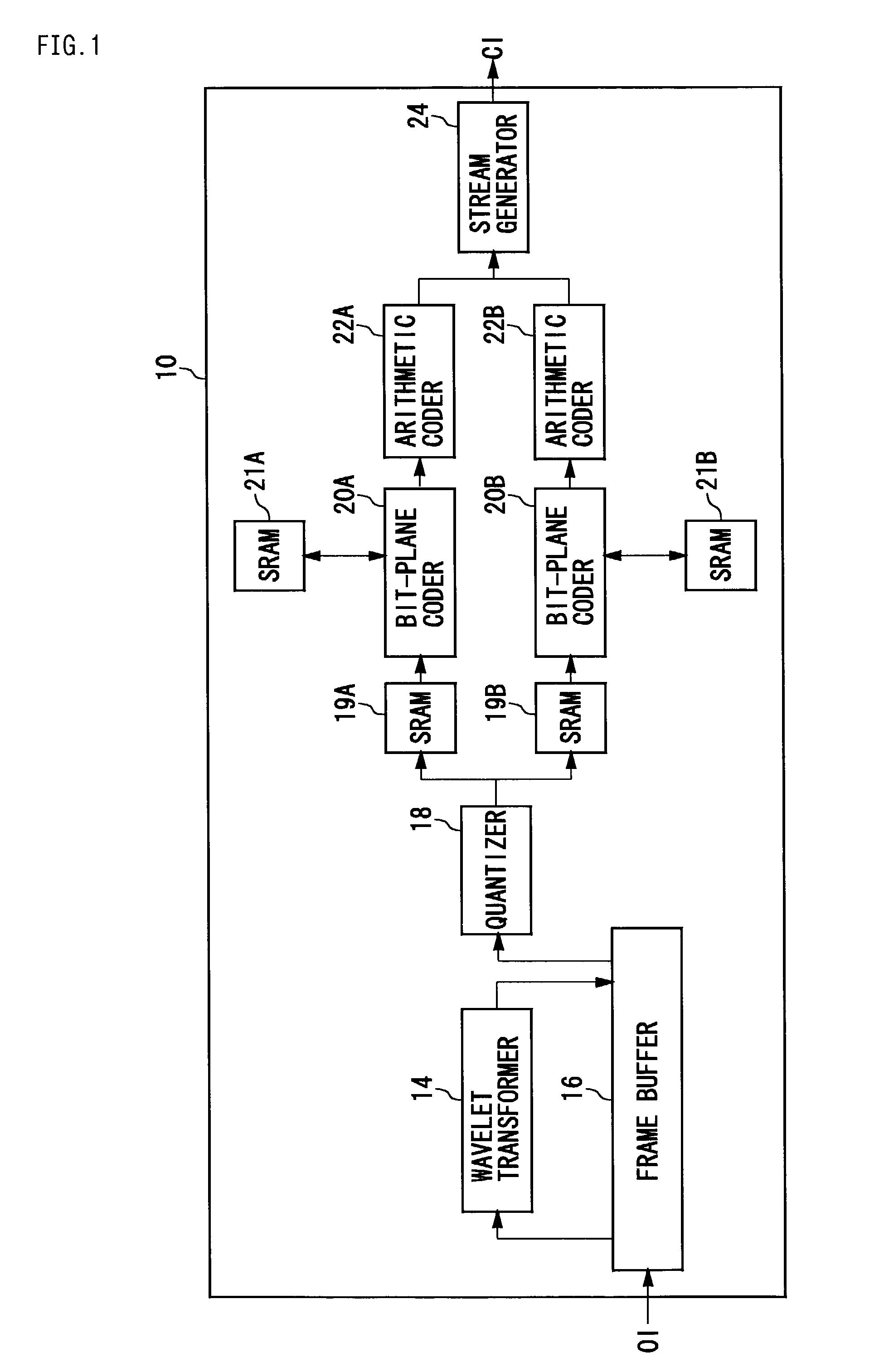
[0041]FIG. 1 shows a structure of an image coding apparatus 10 according to a first embodiment of the present invention. In terms of hardware, this structure can be realized by a CPU, memory and other LSIs. In terms of software, it is realized by memory-loaded programs or the like with image coding functions. Described and shown here are functional blocks that are realized in cooperation with such components. Therefore, it should be understood by those skilled in the art that these functions can be realized in a variety of forms by hardware only, software only or by the combination thereof.
[0042]The image coding apparatus 10 includes a wavelet transformer 14, a frame buffer 16, a quantizer 18, bit-plane coders 20A and 20B, arithmetic coders 22A and 22B and a stream generator 24. At the start of a coding processing, an input image is divided into a plurality of blocks called tiles. Each tile is coded as an independent image, and a bit stream is formed. Thus, an image block correspond...
second embodiment
[0054]FIG. 5 shows a structure of an image coding apparatus 10 according to a second embodiment of the present invention. The structure and operation that differ from the first embodiment will be described hereinbelow. In this second embodiment, a single SRAM 19 is provided for use in storing a code block, and a plurality of planes are processed, in parallel, for coding a single code block. As explained with reference to FIG. 4, the code block stored in an SRAM 19 has seven planes P6 to P0. In the first embodiment, the seven planes are coded, in sequence, starting from plane P6 that corresponds to the most significant bit, but, in the second embodiment, coding is carried out by processing these planes in parallel. Here, an example will be described where the coding of two planes is parallel-processed.
[0055]Two different planes of a code block stored in the SRAM 19 are read out in parallel by two bit-plane coders 20A and 20B; a bit-plane coding is performed on each of the planes; and...
third embodiment
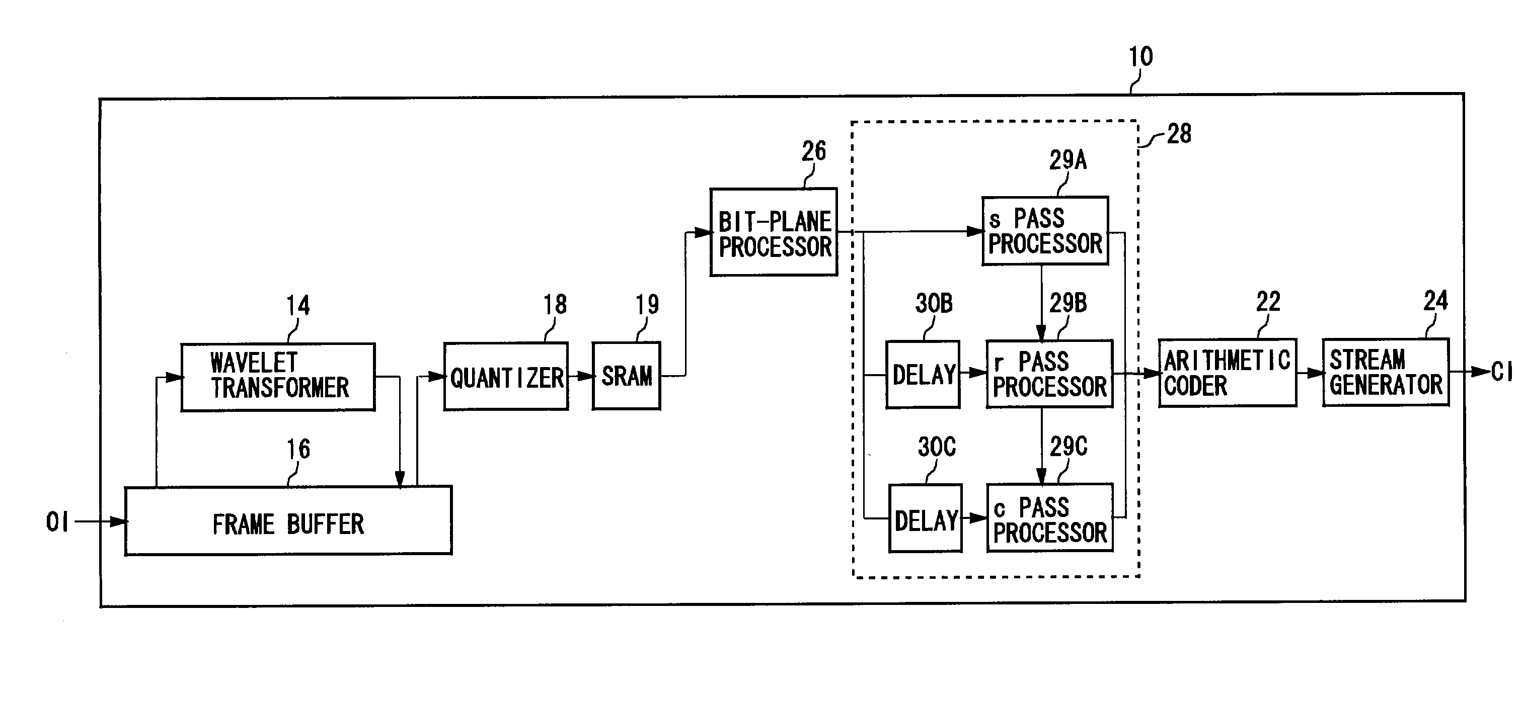
[0064]FIG. 6 shows a structure of an image coding apparatus 10 according to a third embodiment of the present invention. In this third embodiment, similar to the first embodiment, the coding processings of a plurality of code blocks are performed in parallel, but this parallel processing is performed together with a processing of dividing into passes in bit-plane coding (which will be described later). Here, a parallelization of coding processing of three code blocks will be described, in which the description of the structure and operation common to the first embodiment is omitted.
[0065]The wavelet coefficients of the three different code blocks are stored in three SRAMs 19A, 19B and 19C. The wavelet coefficients of the respective code blocks are read out in parallel by three bit-plane processors 26A, 26B and 26C, where each wavelet coefficient is separated into a sign bit and an absolute value thereof, and the absolute value is converted to a binary bit-plane expression. Each bit-...
PUM
 Abstract
Description
Claims
Application Information
 - R&D Engineer
- R&D Manager
- IP Professional
- Industry Leading Data Capabilities
- Powerful AI technology
- Patent DNA Extraction
Browse by: Latest US Patents, China's latest patents, Technical Efficacy Thesaurus, Application Domain, Technology Topic.
© 2024 PatSnap. All rights reserved.Legal|Privacy policy|Modern Slavery Act Transparency Statement|Sitemap