Four-stroke internal combustion engine

a four-stroke, internal combustion engine technology, applied in the direction of lubricant level maintenance, lubrication elements, pressure lubrication, etc., can solve the problems of insufficient lightness, heavy weight of prior four-stroke engines, and inability to be used in operator-carried power tools, etc., to achieve sufficient lightness, low emissions, and economical manufacturing

Inactive Publication Date: 2006-11-14
BRIGGS & STRATTON
View PDF12 Cites 14 Cited by
  • Summary
  • Abstract
  • Description
  • Claims
  • Application Information

AI Technical Summary

Benefits of technology

[0004]Accordingly, there is a need for a four-stroke internal combustion engine that is capable of use in various power tools, and yet is also capable of having low emissions and being sufficiently light to be carried by an operator when desired. What is also needed is a four-stroke internal combustion engine that is capable of operating in many different attitudes of the engine. What is also needed is a four-stroke engine that eliminates the need for an elaborate lubrication system. What is needed is a four-stroke internal combustion engine which accomplishes these features and other features and which is also economical to manufacture.

Problems solved by technology

Electric motors are limited to certain applications due to the available power for products utilizing a cord, and battery longevity for cordless products.
However, previously, it was widely viewed that four-stroke internal combustion engines could only be used for limited applications, such as lawn mowers, snowblowers, generators, or other portable products having wheels.
It was thought that these prior four-stroke engines were too heavy and cumbersome to be used in operator-carried power tools.
Moreover, since it is generally necessary to store oil separate from the gas so that the oil can be used for lubrication, traditional low-cost four-stroke engines were not designed to operate in any position other than a substantially upright position because if the engine was significantly tipped or tilted, the lubricant would foul the engine.

Method used


Image

  • Four-stroke internal combustion engine
  • Four-stroke internal combustion engine
  • Four-stroke internal combustion engine

Examples


Embodiment Construction

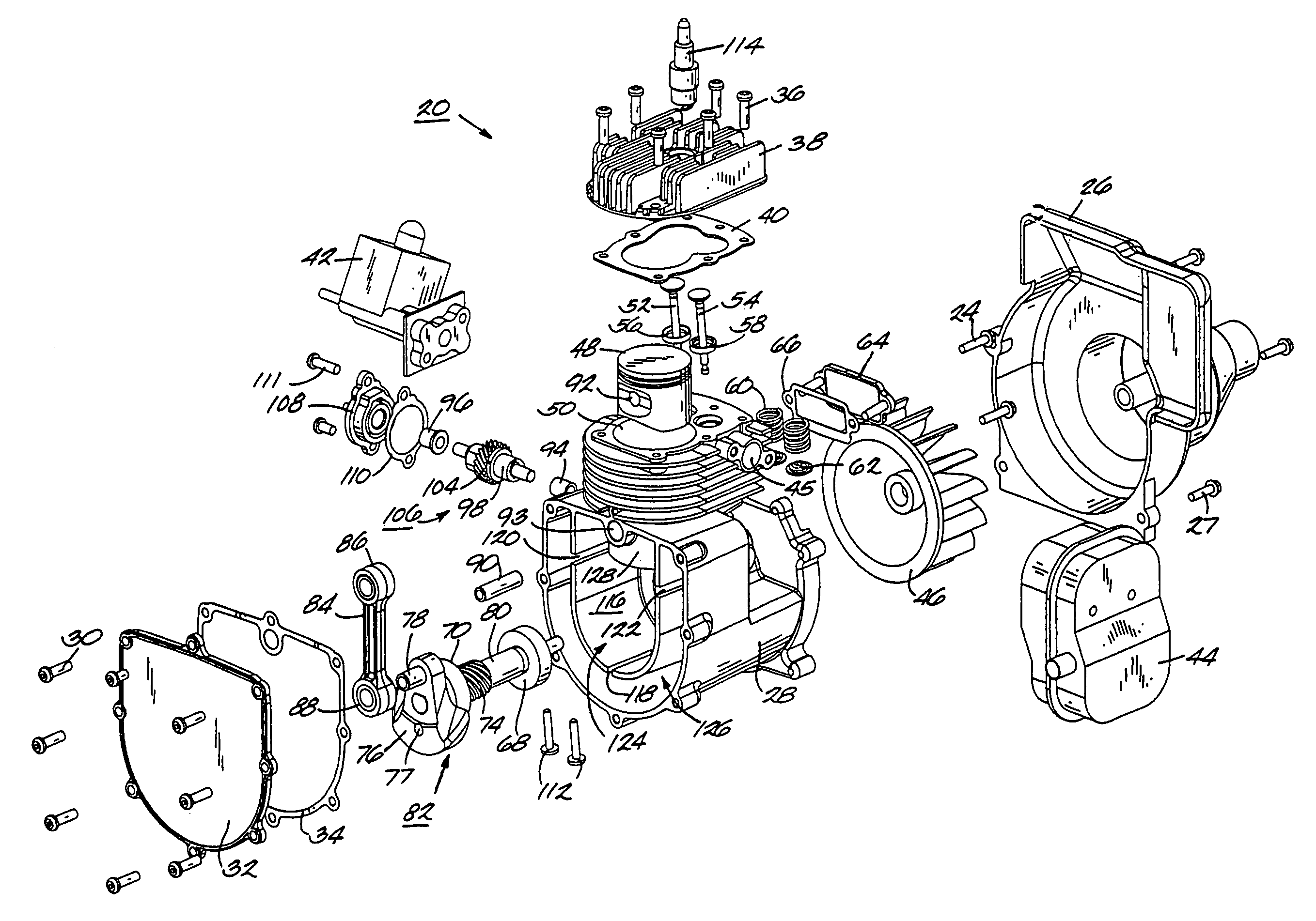
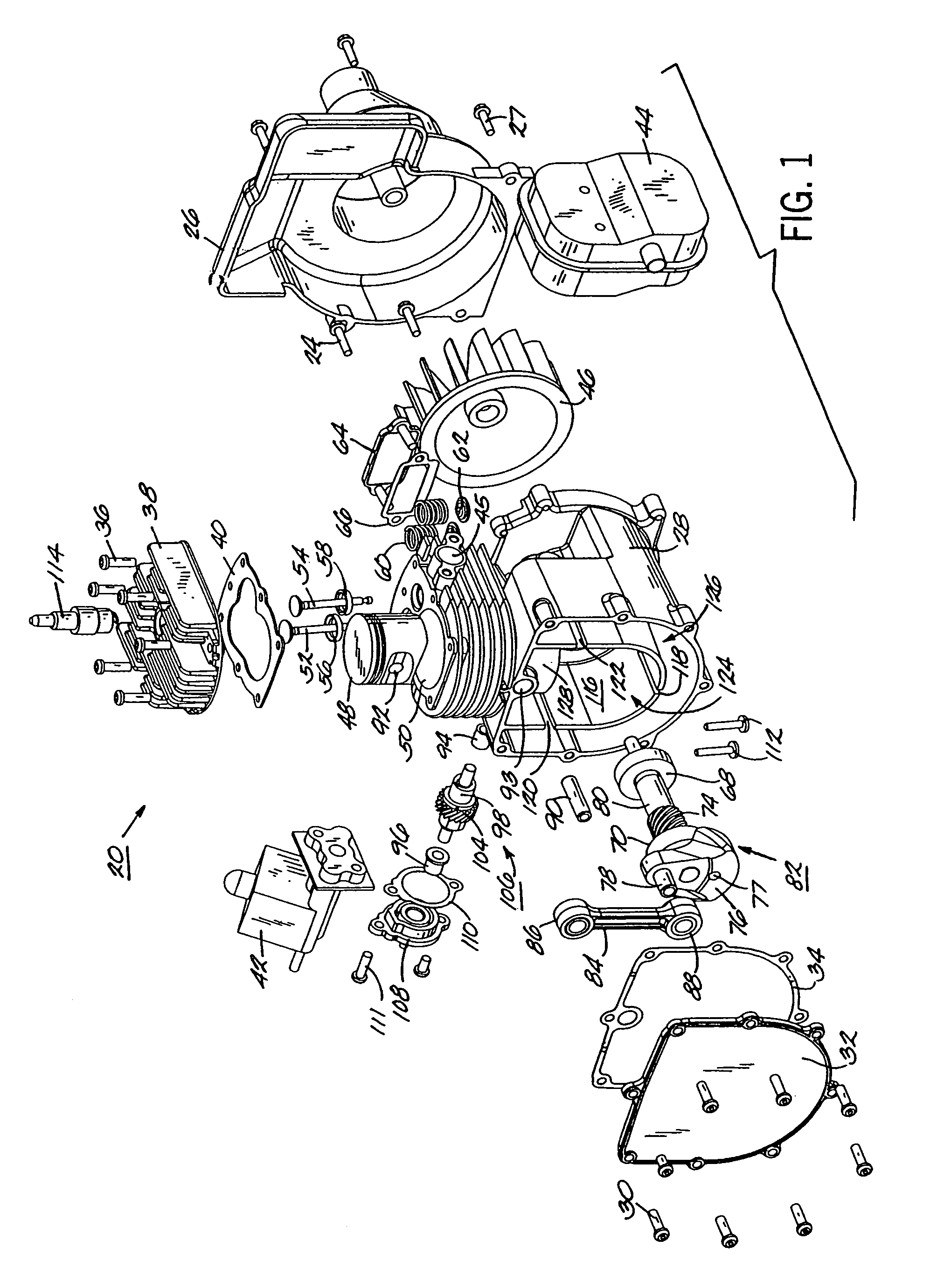
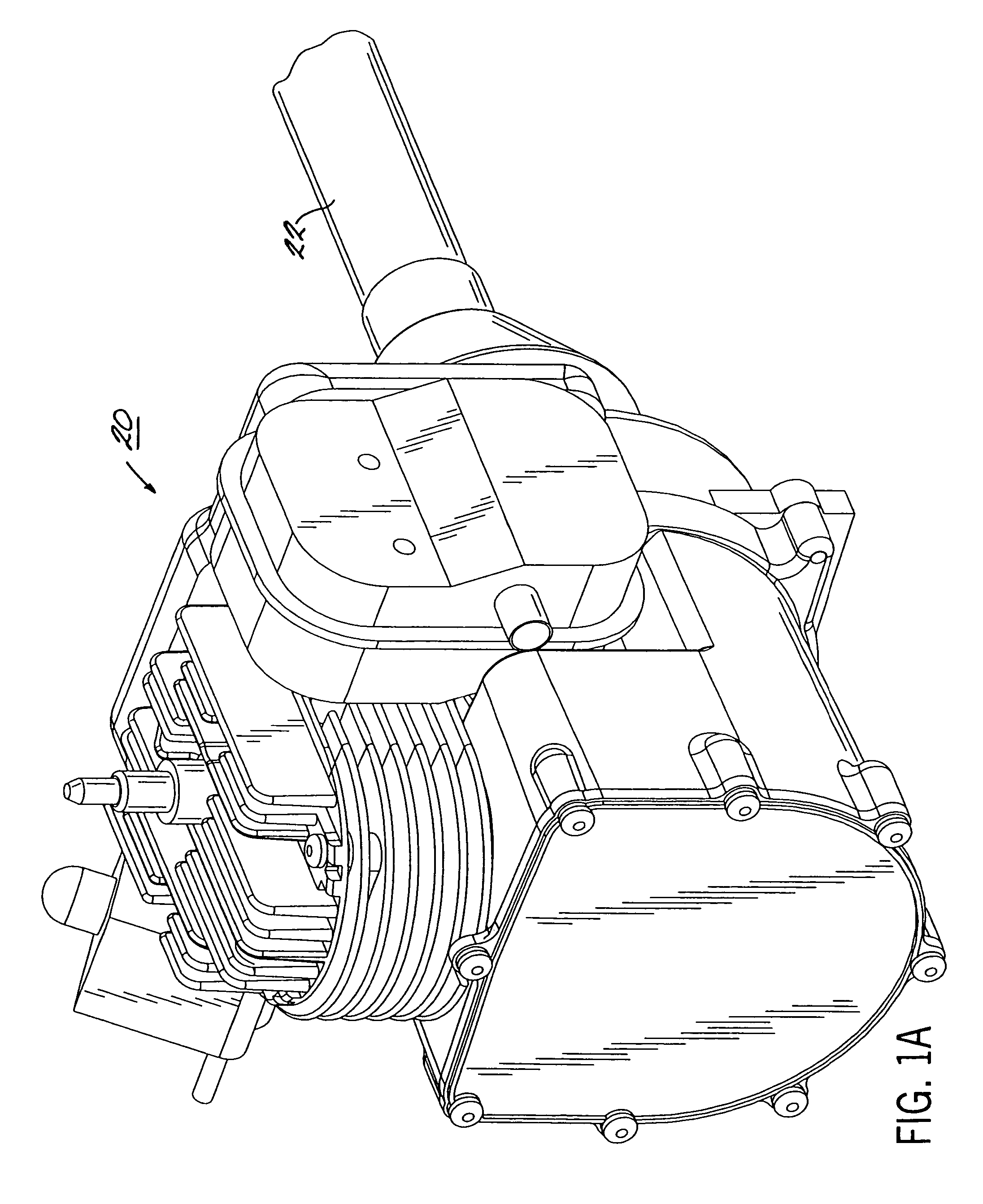
[0073]Illustrated in FIG. 1A of the drawings is a four-stroke internal combustion engine 20 according to the present invention. The engine 20 drives a conventional shaft typically housed in a shaft tube 22 which in turn drives an implement having a rotary head, cutting filament or blade, rotary impeller, or the like, depending on the type of power tool in use (see, e.g., FIG. 19). The shaft arrangement shown in FIG. 1A (and FIG. 19), typically used in conjunction with a hand-held power trimmer, is used for illustrative purposes only and it should be understood that other power tools such as those mentioned previously herein are capable of utilizing the four-stroke engine of the present invention. In other words, generally, the engine according to the present invention is preferably used in an orientation where the implement or working tool has an axis which is substantially parallel with a crankshaft axis. The engine according to the present invention may also be orientated with the...


PUM


Abstract

A four-stroke internal combustion engine is provided that is capable of use in many power tools, including those power tools subjected to tippable applications. The engine includes an oil reservoir and a crank chamber separated by a divider. The divider includes a slot that allows lubricant to move from the oil reservoir into the crank chamber and from the crank chamber into the oil reservoir in response to pressure fluctuations of the engine. The engine can include an insert positioned within the slot to at least partially restrict the slot thereby modifying the lubricant communication between the crank chamber and the oil reservoir through the slot. The insert can be wedge-shaped and at least partially define a passage such that when the insert is positioned within the slot the transfer of lubricant between the crank chamber and the oil reservoir occurs through the passage.

Description

FIELD OF THE INVENTION[0001]The present invention relates, generally, to four-stroke internal combustion engines and, more particularly, to four-stroke internal combustion engines used in trimmers, blowers, vacuums, chain saws, other hand-held power tools, snowblowers, generators, vegetation cutting devices such as lawn mowers, or other outdoor power equipment.BACKGROUND OF THE INVENTION[0002]Many hand-held power tools or other outdoor power equipment are powered by electric motors or two-stroke internal combustion engines. Electric motors are limited to certain applications due to the available power for products utilizing a cord, and battery longevity for cordless products. Conventional two-stroke engines include a lubricating means in which the lubricant is mixed with fuel which allows the engines to operate in any given position such as upright, inclined, sideways or upside down. For example, when using a chain saw, the chain saw is typically capable of use in either an upright,...

Claims


Application Information

Patent Timeline
Patent Type & Authority Patents(United States)
IPC IPC(8): F01M1/00F01M1/04F01M1/06F01M11/06F02B63/02
CPCF01M1/04
Inventor NAGEL, JOHN JEROMEZBIEGIEN, JR., JOHN ALAN
Owner BRIGGS & STRATTON
Why Eureka
Try Eureka