Durable percussion pad effective against noise, silent percussion instrument, silent percussion instrument set and electronic percussion system

Inactive Publication Date: 2006-11-14
YAMAHA CORP
View PDF10 Cites 37 Cited by
  • Summary
  • Abstract
  • Description
  • Claims
  • Application Information

AI Technical Summary

Benefits of technology

[0013]It is therefore an important object of the present invention to provide a percuss

Problems solved by technology

In fact, the acoustic drum sound is so loud that most of the youths worry about the training place.
Nevertheless, the mute cover and training pad make the drum sound thick.
Another drawback is weak restitution at the beats on the pad.
Yet another drawback inherent in the mute for the acoustic drums is that the loudness is uncontrollable.
A drawback inherent in the electronic drum is noise, which is generated at the beats on the drum pad.
The noise is offensive to the ear.
Especially, when the user turns down the volume, the noise strikes the user's ear.
Thus, the noise is the serious drawback in the electronic drums.
This results in fairly soft noise.
On the other hand, the mesh is porous, and the air passes through a lot of holes among the threads.
However, the following problems are encountered in those prior art drum heads.
The problem inherent in the drum head adhered with the damping layer is poor muting characteristics.
Although the prior art drum head with the damping layer is fairly effective against the noise, the noise is louder than the noise h

Method used


Image

  • Durable percussion pad effective against noise, silent percussion instrument, silent percussion instrument set and electronic percussion system
  • Durable percussion pad effective against noise, silent percussion instrument, silent percussion instrument set and electronic percussion system
  • Durable percussion pad effective against noise, silent percussion instrument, silent percussion instrument set and electronic percussion system

Examples


first embodiment

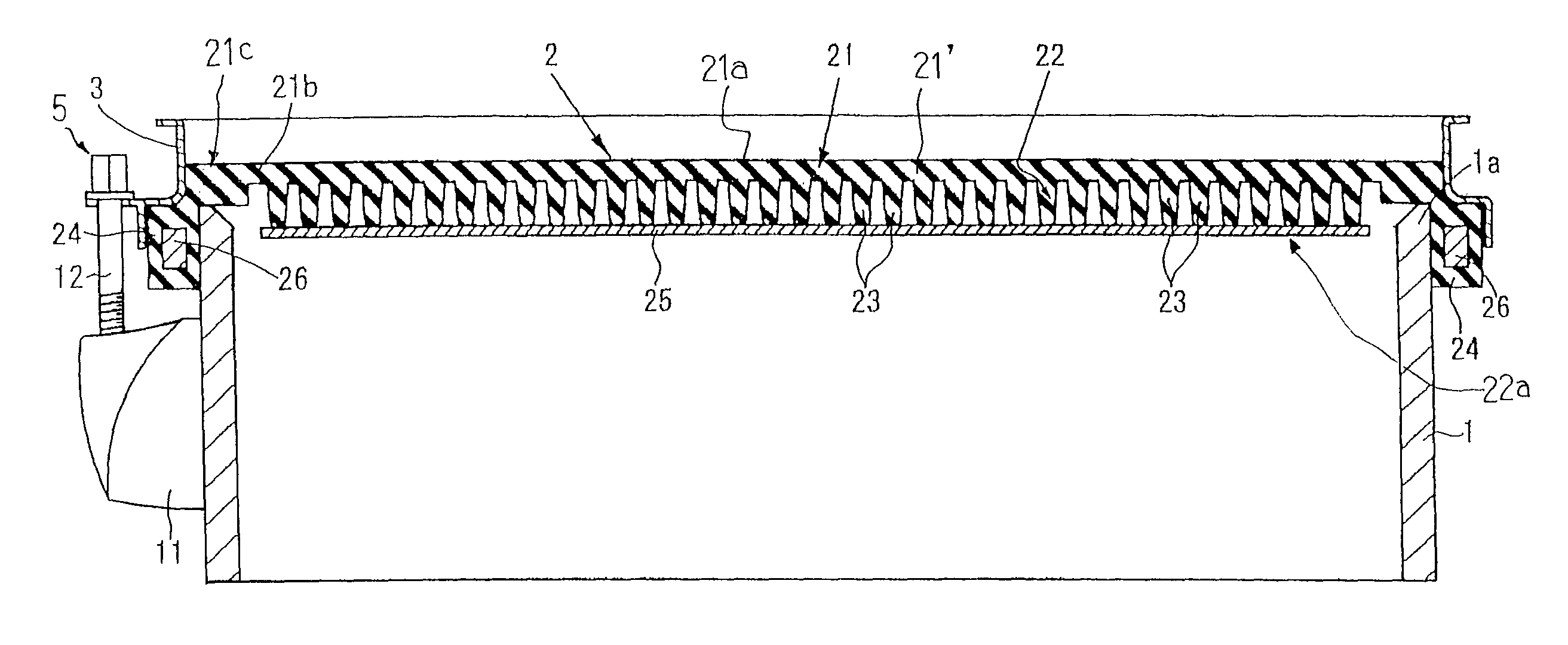
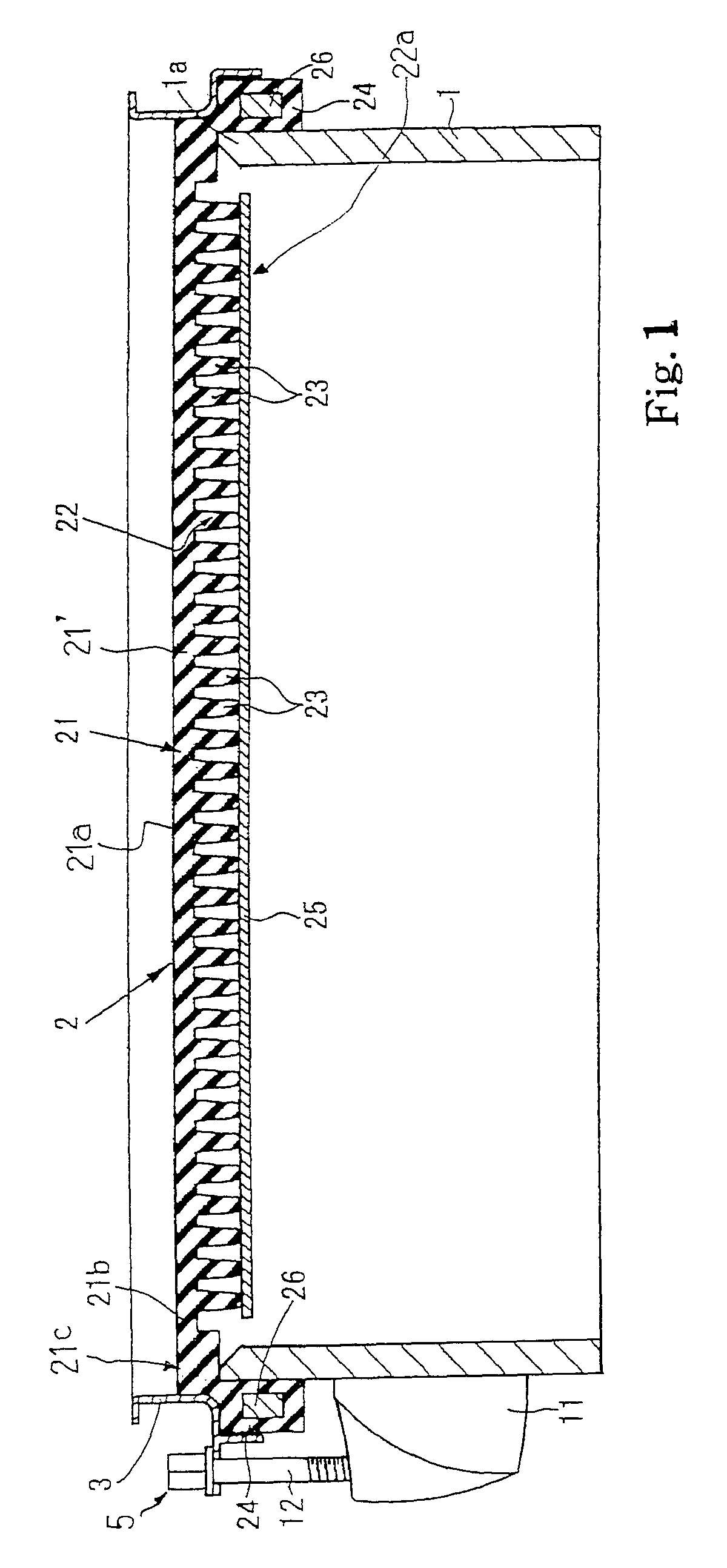
[0053]Referring to FIG. 1 of the drawings, a drum embodying the present invention comprises a shell 1, a drum head 2, a rim 3 and a tension regulator 5. The rim 3 is sometimes called as “hoop”. The drum head 2 is stretched over an opening of the shell 1, and is clamped between the shell 1 and the rim 3 by means of the tension regulator 5. The drum head 2 is of the type having a large damping factor, and, accordingly, suppresses vibrations rapidly. The drum head 2 has a continuous top surface of a non-fabric resilient member so that any friction sound is never produced in the vibrations. The drum head 2 accumulates a large amount of elastic strain energy, and exhibits a large amount of force of restitution at a beat thereon. This results in that drummers feel the sticking work close to that on the ordinary drum head.

[0054]The components 1, 2, 3 and 5 will be described in more detail. The shell 1 has a cylindrical shape, and is open at both ends thereof to the air. The drum head 2 has...

second embodiment

[0077]FIG. 5 shows another drum embodying the present invention. The drum comprises a shell 1A, a drum head 2A, a rim 3A, a tension regulator 5A and a supporter 30A. The shell 1A, drum head 2A, rim 3A and tension regulator 5A are similar to those 1, 2, 3 and 5 of the first embodiment, and, for this reason, the other component parts and portions are labeled with the references designating the corresponding parts and portions of the drum shown in FIG. 1 without detailed description.

[0078]The supporter 30A includes plural supporting brackets 30. The supporting brackets 30 are spaced at regular intervals, and are secured to the inner surface of the shell 1A. An angle plate 30a / 30b, a bolt 31 and a cushion 33 form in combination each of the supporting brackets 30. The angle plate has a horizontal portion 30a and a vertical portion 30b, and the vertical portion 30b is secured to the inner surface of the shell 1A by means of the bolt 31. The cushion 33 is made of sponge, soft synthetic res...

third embodiment

[0080]FIG. 6 shows yet another drum embodying the present invention. The drum implementing the third embodiment comprises a shell 1B, a drum head 2B, a rim 3B and a tension regulator 5B. The shell 1B, rim 3B and tension regulator 5B are similar to those 1, 3 and 5 of the first embodiment, and component parts and portions are labeled with the references designating corresponding component parts and portions of the drum shown in FIG. 1 without detailed description.

[0081]The drum head 2B includes the solid portion 21′, rigid portion 21c, resilient portion 21b and a locally vibratory portion 22B. The solid portion 21′, rigid portion 21c and resilient portion 21b are similar to those of the drum head 2, and no further description is hereinafter incorporated for the sake of simplicity. The locally vibratory portion 22B also includes an accumulating portion 22 and base plate 25, and an intervening sheet 28 is added to the locally vibratory portion 22B. The pillars 23 are adhered to the upp...


PUM


Abstract

A drum head is broken down into a head body, which in turn is broken down into a solid portion and an accumulating portion, and a rigid base plate; the solid portion offers a beaten surface to a drummer, and the accumulating portion or an array of pillars and the base plate form in combination a locally vibratory portion; when a drummer strikes the beaten surface with a stick, the solid portion caves in for accumulating a part of the impact load, and gives rise to resilient deformation of the pillars beneath the cave so that another part of the impact load is accumulated in the deformed pillars as the elastic strain energy; the elastic strain energy is released through the local vibrations of the pillars, and the vibration energy is transmitted to a small amount of the air therearound so that the noise is faint.

Description

FIELD OF THE INVENTION[0001]This invention relates to a percussion instrument and, more particularly, to a percussion pad, a percussion instrument equipped therewith, a set of percussion instruments and an electronic percussion system using the percussion instrument.DESCRIPTION OF THE RELATED ART[0002]Drums are typical examples of the percussion instrument. The drums are broken down into two categories. Although the drums of both categories have respective drum heads to be beaten by drummers, the beats are produced through different processes. The drum head serves as a percussion pad in the drum, and terms “drum pad” and “skin” are synonyms of the drum head. The drums in the first category are hereinafter referred to as “acoustic drums”, and the drum sound is generated through the vibrations of the drum head. On the other hand, the drums of the other category are referred to as “electronic drums”, and the drum sound is generated through an electronic data processing repeatedly initi...

Claims


Application Information

Patent Timeline
IPC IPC(8): G10D13/02G10H1/00G10H3/14
CPCG10D13/024G10D13/027G10D13/02G10D13/20G10D13/26G10H3/14
Inventor MARUHASHI, MASAHIKOSANDO, TAKASHIKONDOH, MOTOYA
Owner YAMAHA CORP
Why Eureka
Try Eureka