Apparatus for lapping thin film magnetic heads

a technology of thin film and magnetic heads, applied in the field of lapping apparatuses, can solve the problems of increasing the required characteristics, reducing the yield rate, and affecting the quality so as to increase the yield rate in the manufacturing process of the magnetic head slider, not to make the output and asymmetry characteristics bad

Active Publication Date: 2008-02-05
SAE MAGNETICS (HK) LTD +1
View PDF17 Cites 11 Cited by
  • Summary
  • Abstract
  • Description
  • Claims
  • Application Information

AI Technical Summary

Benefits of technology

[0015]The invention has been made in view of the above-mentioned problem, and it is therefore an object of the present invention to provide a lapping method and apparatus that increases the yield rate in the magnetic head slider manufacturing process, but does not make output and asymmetry characteristics bad.
[0016]Another object of the present invention is to provide a lapping method and apparatus that reducing the variation of the profile of magnetic head sliders.
[0019]As mentioned above, it is required to lap only one bar fixed on one holding jig, which is mounted on one lapping apparatus, when the lapping is performed by use of the RLG method. Therefore such applies a strong load or stress to the bar. The study of inventors of this application shows that bad characteristic of the output and / or asymmetry in the manufacturing process and big variation of between profiles are caused by the load or stress applied to the bar during the lapping operation. Therefore to reduce the load applied to the bar, such as the machine load, drag from the lapping plate and frictional force with the lapping plate, at least one member for load sharing, which is lapped together with the bar, is provided to distribute the load or stress. As a result, both playback output and asymmetry characteristic are improved. Also the defect occurring on the surface of the lapping plate and the magnetic head slider, such as scratches and abrasions are reduced, and variation between profiles as well as amount of recess are reduced. Therefore, the yield rate is significantly improved in the manufacturing process of the magnetic head sliders and HGA.

Problems solved by technology

However, since amount of lapping (amount of height) is controlled by the lapping time, it is not possible to change the amount of lapping by each bar to be lapped at the same time, and therefore it causes the serious problem that the characteristics of the magnetic head slider to be manufactured vary widely.
Therefore following problems are caused by use of RLG method.(1) As the thin film magnetic head advances, the required characteristics become more severe, so that in the magnetic head slider manufacturing process, the yield rate is decreasing, because a lot of magnetic head sliders are rejected in the quasi static test (QST), especially rejected by bad output and asymmetry characteristics.
It decreases the yield rate in the head gimbal assembly (HGA) process, in which the magnetic head sliders are attached to suspension arms.(2) Similarly, since it is required for ABS surface to finish with high accuracy, processing becomes more difficult.
Therefore such leads to decreasing of the yield rate in the HGA process.

Method used


Image

  • Apparatus for lapping thin film magnetic heads
  • Apparatus for lapping thin film magnetic heads
  • Apparatus for lapping thin film magnetic heads

Examples


Embodiment Construction

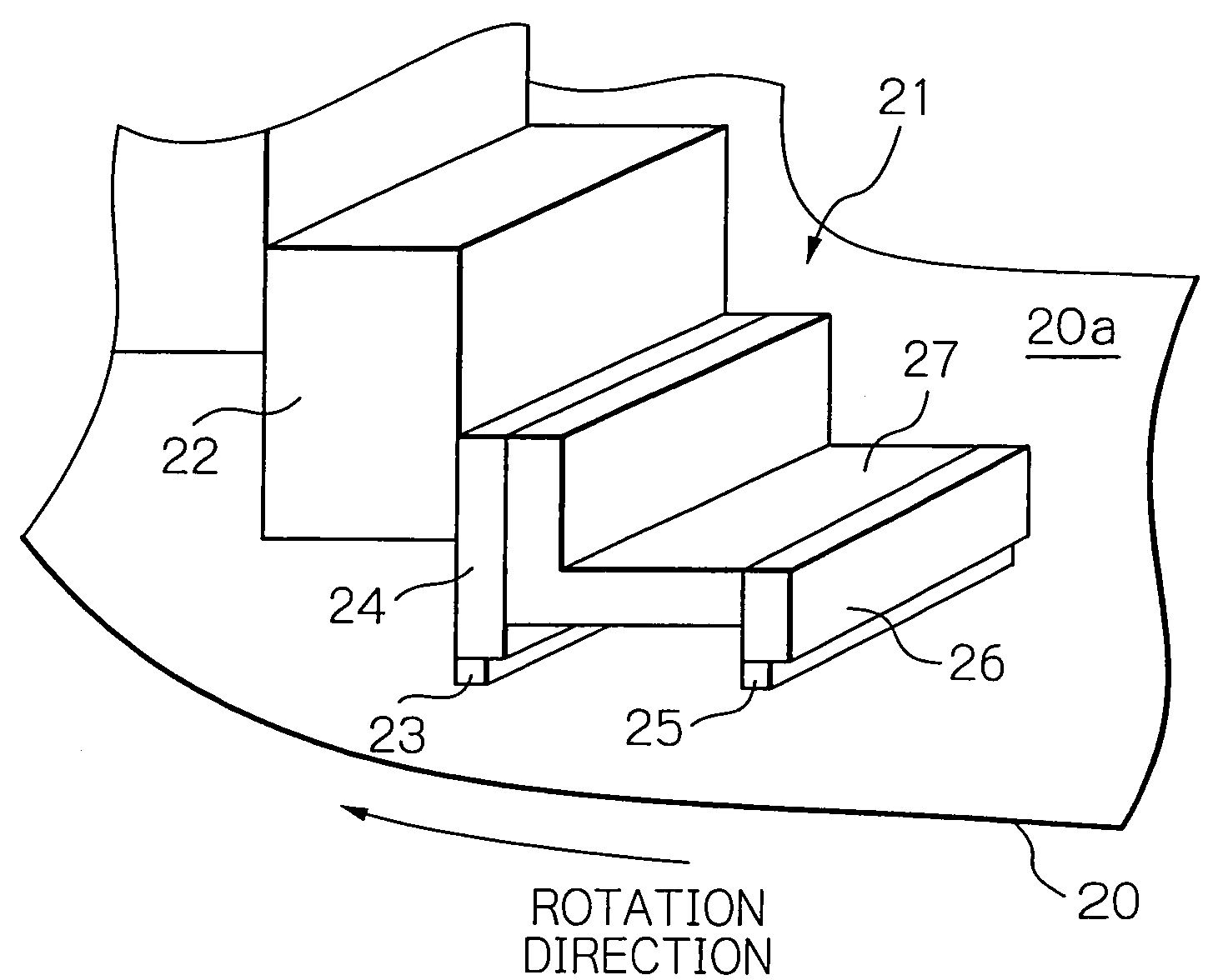
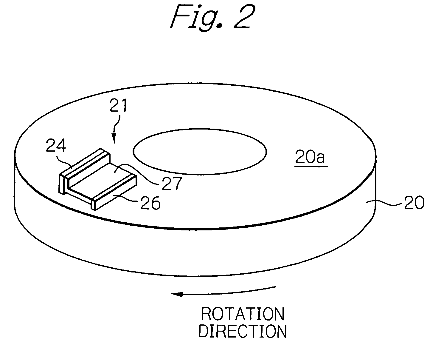
[0041]FIG. 2 is a perspective view showing an embodiment of a lapping apparatus schematically according to the present invention, and FIG. 3 is an enlarged perspective view of the lapping apparatus shown in FIG. 2, for showing the detail of the holding jig block.

[0042]In the FIG. 2 and FIG. 3, reference 20 is a lapping plate, which rotates the direction indicated by the arrow, and reference 21 is a holding jig block or assembly, whereby a holding jig in the holding jig block 21 holds the bar to be lapped, and reference 22 is a transfer tool, which supports the holding jig in the holding jig block 21, and provides the signal line to transmit the signal from a lapping amount sensor, which is described later, to controller of the lapping apparatus.

[0043]The holding jig block 21 mainly includes a rectangular column shaped jig 24 (a first jig), which holds a bar 23 to be lapped, and a dummy bar jig 26 (a second jig), which holds a dummy bar 25, and a lapping keeper 27, which is fixed to ...


PUM

PropertyMeasurementUnit
frequencyaaaaaaaaaa
frequencyaaaaaaaaaa
yield rateaaaaaaaaaa

Abstract

A lapping method and apparatus is provided that increases the yield rate in the magnetic head slider manufacturing process. According to the invention, an apparatus for lapping thin film magnetic heads includes a jig block and a lapping plate. The jig block includes a first jig which holds a bar to be lapped, and second jig which holds a member for load sharing. The lapping plate is movable relative to the first jig and the second jig, and is contactable with the surface to be lapped of the bar held by the first jig and the member for load sharing held by the second jig for lapping.

Description

PRIORITY CLAIM[0001]This application claims priority from Japanese patent application No. 2003-369205, filed on Oct. 29, 2003, which is incorporated herein by reference.BACKGROUND OF THE INVENTION[0002]1. Field of the Invention[0003]The present invention relates to a lapping apparatus and method used in the lapping process for the manufacture of thin film magnetic heads.[0004]2. Description of the Related Art[0005]A magnetic head slider used in a magnetic disc provides at least one thin film head element, which is located at a trailing edge (exhaust side of the air flow) of the magnetic head slider, and a magnetic head slider is provided such that such floats above the surface of the magnetic disc by rotating the magnetic disc.[0006]In the manufacturing process, a plural of magnetic head elements are formed on a wafer (substrate), and the wafer is cut into a plurality of bars, which have a plurality of magnetic head elements in line, and then lapping of the air bearing surface (ABS)...

Claims


Application Information

Patent Timeline
Patent Type & Authority Patents(United States)
IPC IPC(8): B24B49/00B24B51/00B24B9/00B24B37/04B24B37/07B24B37/30G11B5/39
CPCB24B37/048B24B37/30Y10T29/49048
Inventor FUJII, RYUJIMATSUKUMA, HIROKI
Owner SAE MAGNETICS (HK) LTD
Why Eureka
Try Eureka