Optical apparatus

a technology of optical imaging and optical components, applied in the field of optical imaging apparatus, can solve the problems of unsuitable, unsuitable, unacceptably large diameter of the front elements of simple existing optical apparatus, and achieve the effect of less sensitive to manufacturing tolerances, high optical manufacturing tolerances, and typical optical strength of negatively distorting lenses

Inactive Publication Date: 2006-11-14
THALES OPTICS
View PDF8 Cites 10 Cited by
  • Summary
  • Abstract
  • Description
  • Claims
  • Application Information

AI Technical Summary

Benefits of technology

[0023]Where all of the optical elements of the second lens system are located before the aperture stop of the optical apparatus of the present invention, the optical strength of the negatively distorting lenses is typically required to be very high in order to effect the required distortion in the intermediate image. However, it has been found that in such an arrangement the performance of those lens elements of the objective lens system responsible for the substantial negative distortion of the intermediate image tends to be highly sensitive to optical manufacturing tolerances.
[0024]Consequently, in the present invention, at least one optical element of the second lens system may impose a substantial degree of negative distortion on the final image. Thus, in splitting-up and separating the image (negatively) distorting optical elements between the objective lens system and the second lens system, the power required of the negatively distorting lenses has been found to be less than is the case where all negatively distorting lenses are located in the objective lens system. This has also been found to provide an optical system which is less sensitive to manufacturing tolerances and thereby may provide improved performance.

Problems solved by technology

However, in many infra-red imaging applications it is unnecessary or undesirable to require that a viewable image be formed by eyepiece optics.
The objective lenses such as disclosed in GB2190761B employ an aperture stop placed before the objective lens (i.e. in front of the optical train) and are, therefore, not suited to those electronic detector systems which have a requirement for an aperture stop to be located well towards the rear of the optical train.
Indeed, the location of the aperture stop towards the rear of the optical train typically leads to unacceptably large diameters for the front elements of simple existing optical apparatus.

Method used


Image

  • Optical apparatus
  • Optical apparatus
  • Optical apparatus

Examples


first embodiment

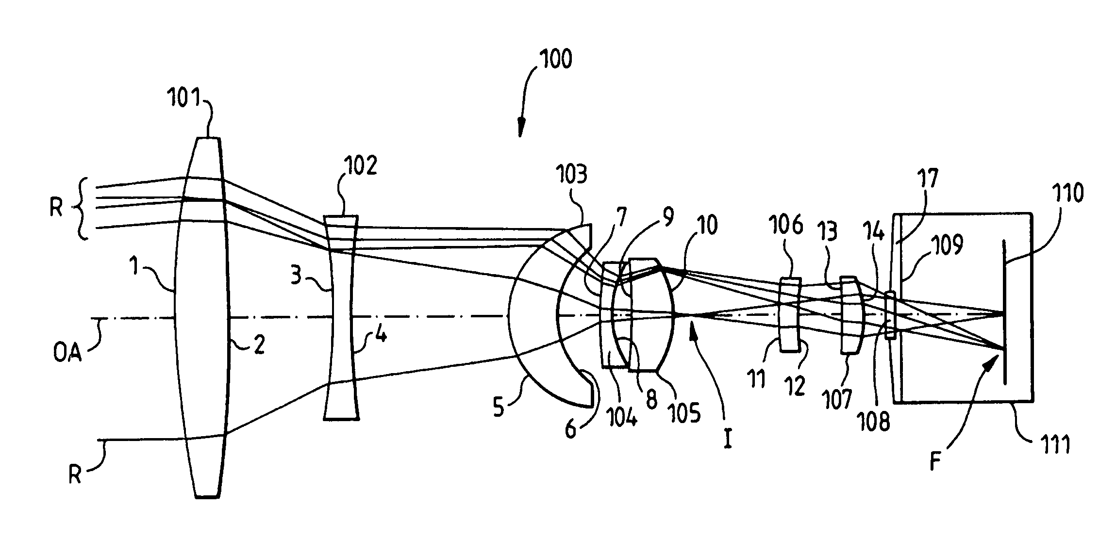
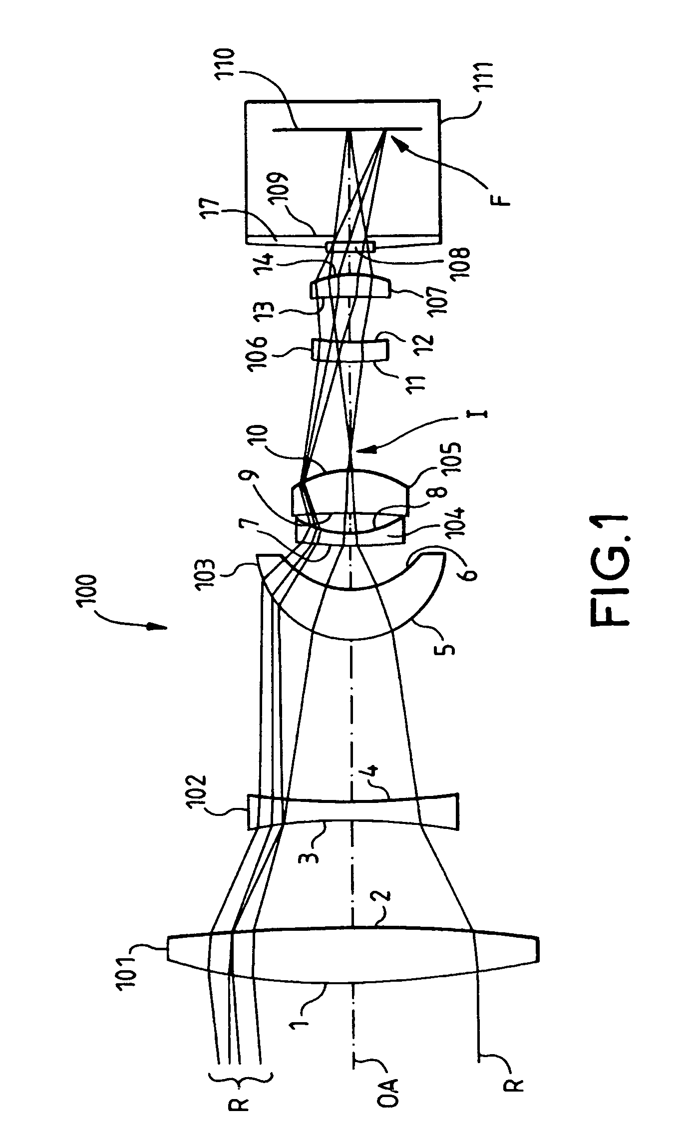
[0050]FIG. 1 illustrates the present invention in which the optical apparatus, generally denoted 100, is an infra-red imaging apparatus and operates in the 4.0–5.0 μm infra-red waveband. The apparatus 100 comprises an objective lens system in the form of an optical train of lens elements arranged along a common optical axis OA, and consisting of a first (i.e. leftmost in FIG. 1) lens element 101, three successive intermediate lens elements 102, 103 and 104, and a terminal lens element 105. Following this train of objective lens elements, and on the optical axis OA, is a train of relay lens elements consisting of a first relay lens element 106, and a terminal relay lens element 107. A dewar 111 is placed on optical axis OA beyond the terminal lens element 107. The dewar has a window 108 and houses an aperture stop 109 and an electronic infra-red image detector 110. The dewar assembly is cooled by a suitable means (not shown) which cools both the detector 110 and the aperture stop 109...

second embodiment

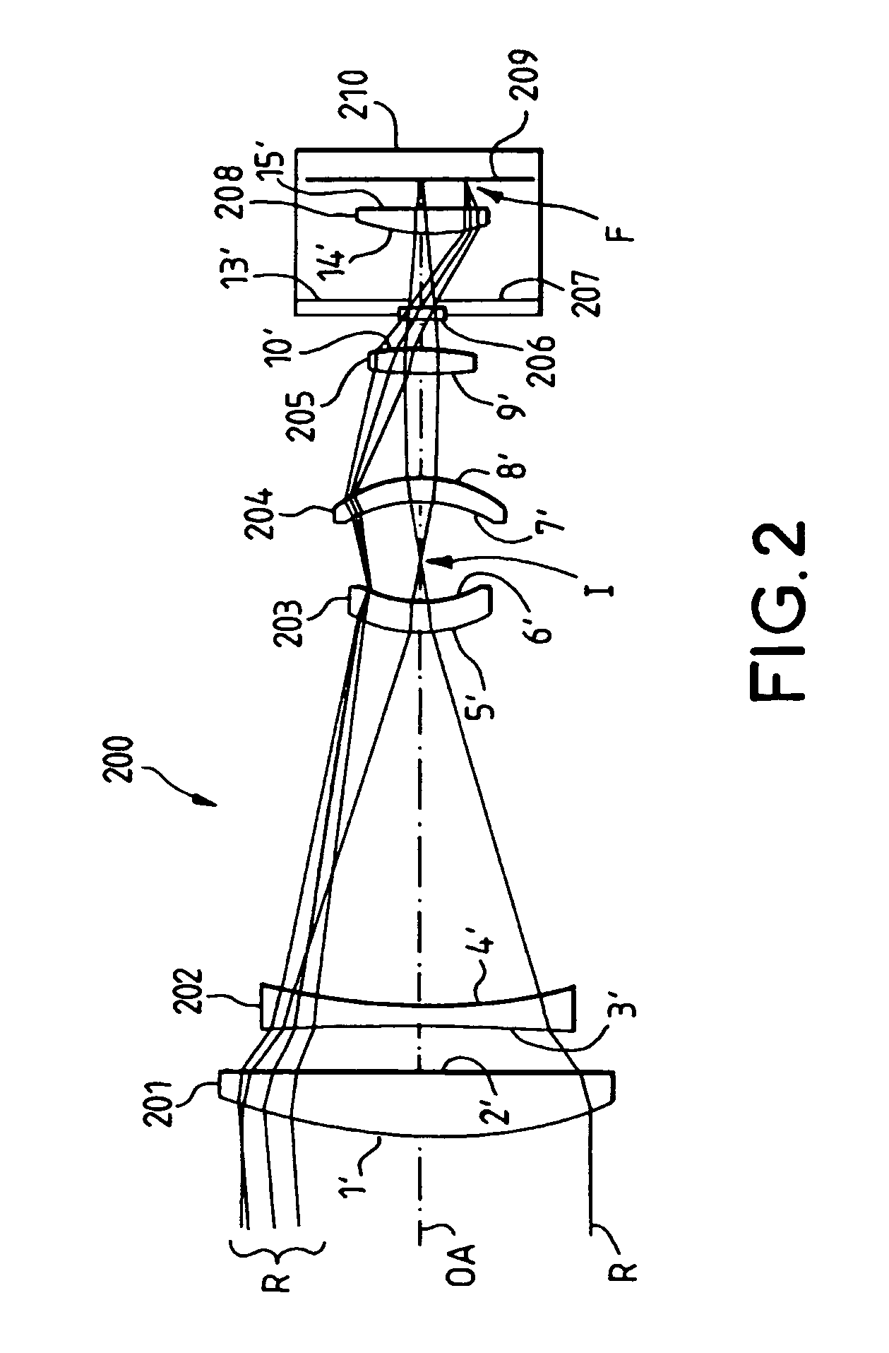
[0068]the present invention, as illustrated in FIG. 2, may provide an optical design which is less sensitive to tolerances and may provide an even greater level of distortion.

[0069]Referring to FIG. 2, there is shown an optical apparatus 200 having a three element objective lens system having a first lens element 201 with a spherical front surface 1′, and a flat rear surface 2′. The second lens element 202 carries a spherical surface 3′ and an aspheric surface 4′, while the terminal lens element 203 of the objective system carries a spherical surface 5′ and an aspheric surface 6′. This objective lens system is arranged to form an intermediate image I after the terminal lens element 203, the intermediate image being substantially negatively (“barrel”) distorted principally by the terminal objective lens element.

[0070]A three element relay lens system is then provided in the optical train of the apparatus by relay lens elements 204, 205 and 208. The relay lens system begins immediate...


PUM


Abstract

The present invention provides an optical apparatus including an objective lens system for focusing optical radiation from a scene or object into an intermediate image and has at least one lens element which imposes a substantial degree of negative distortion on the intermediate image. The invention also provides a second lens system for focusing optical radiation from the intermediate image into a final image and an aperture stop for limiting the optical radiation forming the final image. The aperture stop is located between the final image region in which the final image is formed or to be formed and the lens element of the second lens system most distant from the final image region.

Description

FIELD OF THE INVENTION[0001]The present invention relates to optical imaging apparatus, and particularly, though not exclusively, to apparatus for imaging infra-red radiation.DESCRIPTION OF PRIOR ART[0002]In forming a viewable image of an object a typical optical imaging apparatus employs an objective lens to focus optical radiation from the object into an image of thereof for subsequent viewing. Where the optical radiation is weak or invisible (such as infra-red radiation) it is often necessary to employ intermediate image detecting means to detect the weak image, or to detect an image formed from invisible radiation.[0003]Many optical imaging methods rely on the use of electronic image detectors for this purpose, as does the optical imaging apparatus disclosed in GB2190761B. In GB2190761B, an optical imaging apparatus employs an intermediate infra-red detector, in the form of an infra-red staring array, to detect an invisible infra-red image formed by an objective lens. The detect...

Claims


Application Information

Patent Timeline
Patent Type & Authority Patents(United States)
IPC IPC(8): G02B9/00G02B13/16G02B27/00
CPCG02B13/16G02B27/0037G02B27/4211G02B27/4216
Inventor KIRKHAM, ANTHONY JOHN
Owner THALES OPTICS
Why Eureka
Try Eureka