Optical waveguide

a waveguide and optical technology, applied in the field of optical waveguides, can solve the problems of noise and cross-talk between individual optical signals, limit the effective distance over which optical signals can be transmitted, and exhibit characteristics of optical fibres, so as to reduce the kerr effect and increase the diameter of the mode field

Inactive Publication Date: 2006-11-14
RPX CLEARINGHOUSE
View PDF8 Cites 18 Cited by
  • Summary
  • Abstract
  • Description
  • Claims
  • Application Information

AI Technical Summary

Benefits of technology

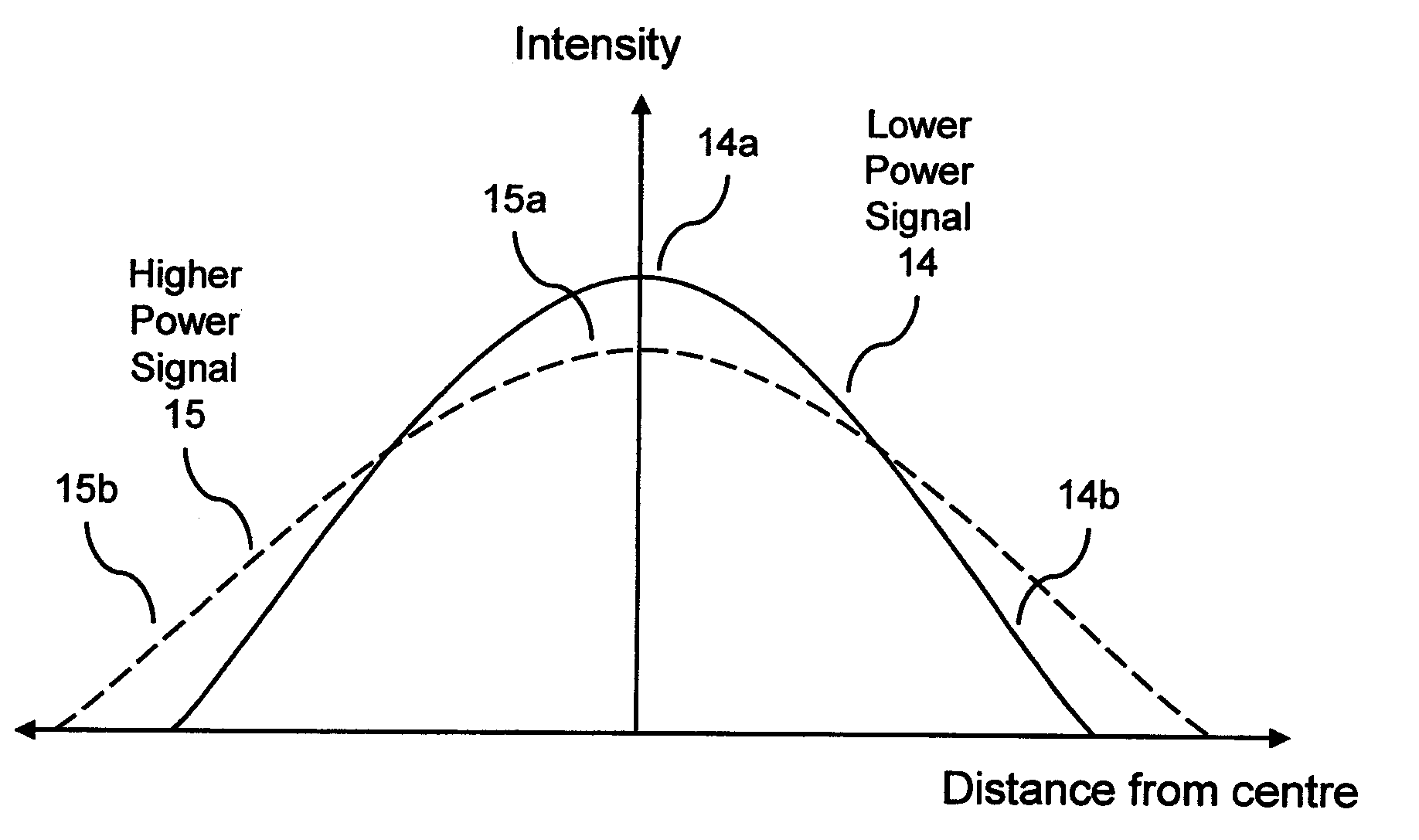
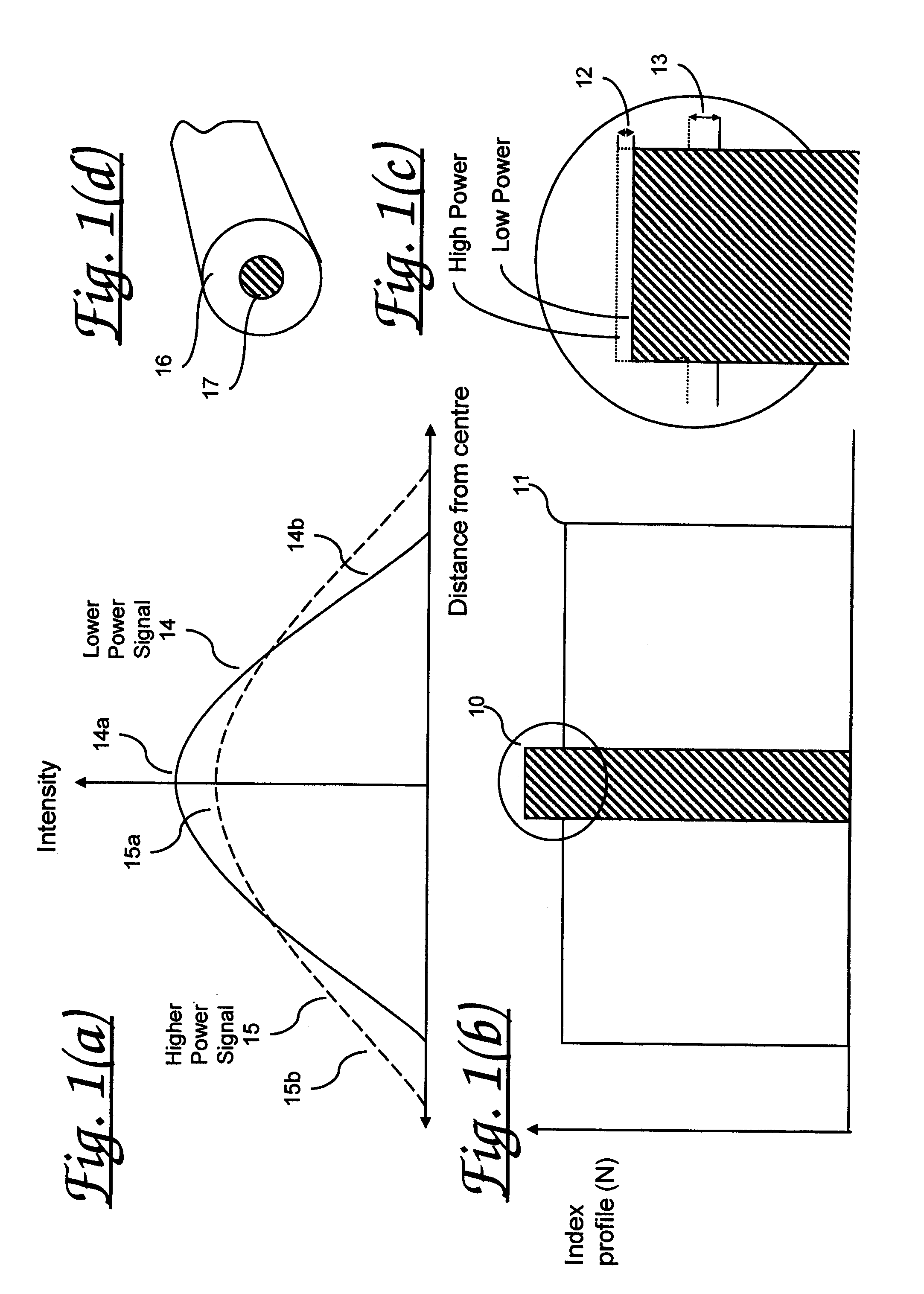
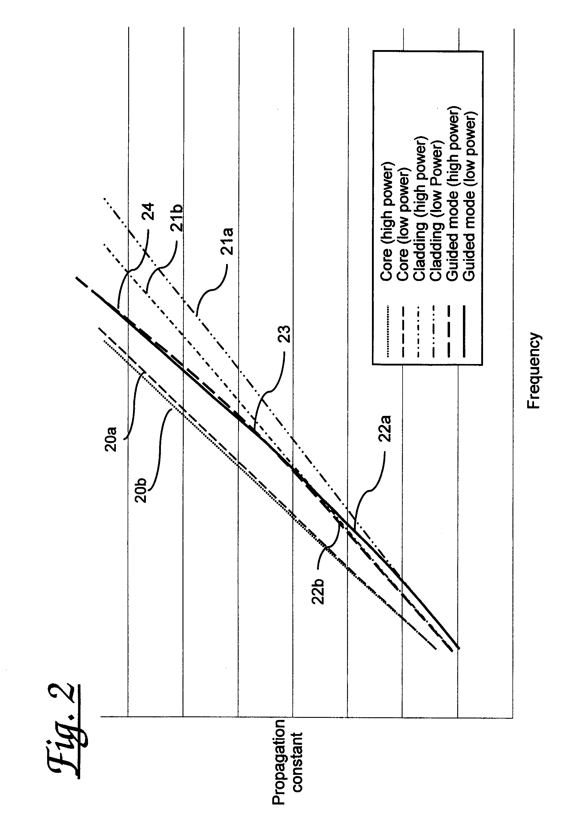
[0057]Advantageously, varying mode field diameter with signal power compensates for nonlinear effects, including the Kerr effect.
[0058]Advantageously, this compensates for the reduced Kerr effect due to increasing mode field diameter at longer wavelengths. This is particularly useful for broadband operation of the waveguide.

Problems solved by technology

However, known optical media (for example optical fibres) are known to exhibit characteristics which limit the effective distance over which optical signals can be transmitted without requiring detection and regeneration.
These non-linear effects are caused by interactions between light waves travelling in the fibre, and can result in both noise and cross-talk between individual optical signals.
Whilst in absolute terms such effects are relatively weak in optical fibres, they do accumulate over long distances.
This accumulation effectively imposes practical limits on the length of optical transmission media from which optical signals can be reliably recovered using known technology.
However, the optical reception and re-transmission apparatus required at such intermediate points may be complex, costly, physically bulky, and may require ongoing expense arising both from powering costs and from maintenance costs.
Clearly such non-linear characteristics exhibited by known optical fibres represent a significant limit to system performance.
Whilst some attempts (for example Large Effective Area Fibre (LEAF), an index profile which results in a larger than average mode field diameter) have been made to overcome Kerr effects these currently provide only small improvements to performance.
This effectively precludes compensation using discrete devices, (unless located every few meters, in which case, the splice losses in to the signal path would be prohibitive).

Method used


Image

  • Optical waveguide
  • Optical waveguide
  • Optical waveguide

Examples


third embodiment

[0107]A third embodiment, illustrated in FIG. 4(c), employs a two-dopant fibre design. This arrangement comprises a doped core 46 surrounded by a doped annulus 47 within a cladding material 48, 49. In the case illustrated the doped core 46 has a higher refractive index 40 than that 42 of the annulus 47 which, in turn, has a higher refractive index than that 41, 43 of the surrounding fibre. The prime requirement is to achieve an increased mode field diameter with power, and this can be achieved by either increasing index 42 of annulus 47, or increasing the index 41 of annulus 49 (the inner cladding) relative to the index of the core 46. Suitable dopants include Silicon, Germanium and Fluorine or other suitable elements together with Oxygen to form the oxides such as Silica, Germania etc. Fluorine has the valuable property as a dopant, that it reduces the index of the Silica, and that increased concentration reduces the nonlinearity. For Germania, both increase. Fluorine is valuable s...

second embodiment

[0115]FIG. 5(b) shows a graph of refractive index, N, across a cross-section of such a fibre. The periodic portion of the structure comprises successive bands 51, 52 of differing refractive index arranged around the core 50. In particular, there are instances of successive bands in which the refractive index 51 of the inner band is lower than that 52 of the outer band as was the case in the second embodiment between the core and the doped annulus.

[0116]The dimensions of the periodic structure should be such as to cause transverse resonance (of the forward propagating field) within the periodic structure, and can be predicted (designed) using numerical simulation tools well known to those practiced in the art of fibre design. Adjacent bands of the periodic structure may also exhibit different variations of refractive index with signal power, so that as the signal power varies, so the difference in refractive index between successive bands also varies. Increasing the index of layers 5...


PUM

PropertyMeasurementUnit
refractive indexaaaaaaaaaa

Abstract

An optical fiber for communications systems, the fiber being designed to ensure a compensation of Kerr effects. The fiber has a profile which ensures that changes in power produce changes in distribution of power between core and cladding, such that the phase change associated with the changed spatial distribution of the power, is equal and opposite to the phase change due to Kerr Effect.

Description

FIELD OF THE INVENTION[0001]The present invention relates to optical wave guides, in particular optical fibre waveguides, as used for example in optical communications systems, and to related methods and apparatus and to optical signals conveyed over such waveguides.[0002]It is known to use optical communications media to carry optically modulated data over great distances in communications networks. However, known optical media (for example optical fibres) are known to exhibit characteristics which limit the effective distance over which optical signals can be transmitted without requiring detection and regeneration. Such characteristics include those induced by the Kerr Effect, by which the refractive index of an optical medium varies according to the intensity of the optical signal conveyed through the medium. Where the signal is a compound signal comprising multiple individual optical signals multiplexed over a common optical medium, changes in refractive index are related to th...

Claims


Application Information

Patent Timeline
Patent Type & Authority Patents(United States)
IPC IPC(8): G02B6/02G02B6/00G02B6/032G02B6/036G02F1/35
CPCG02B6/023G02B6/03644G02B6/03688G02B6/03694G02F1/3511
Inventor EPWORTH, RICHARD EHANDEREK, VINCENTROBINSON, ALAN
Owner RPX CLEARINGHOUSE
Why Eureka
Try Eureka