Gas turbine power augmentation method

a technology of gas turbines and power augmentation, which is applied in steam engine plants, mechanical equipment, machines/engines, etc., can solve the problems of limited water potential for combustor expansion, limited amount of power output potential increase, and damage to gas turbines, so as to increase the mass flow rate and increase the power output of gas turbines.

Active Publication Date: 2006-11-21
PRAXAIR TECH INC
View PDF18 Cites 13 Cited by
  • Summary
  • Abstract
  • Description
  • Claims
  • Application Information

AI Technical Summary

Benefits of technology

[0007]The present invention provides a method of augmenting the power of a gas turbine having a compressor to compress an air stream, combustors to combust fuel and thereby add heat to the air stream after compression and an expander to receive the compressed air stream after having been heated. In accordance with the method, a gas is compressed in a plurality of stages of an auxiliary compressor. Water is injected into at least one of the stages so that the auxiliary compressor produces a vapor containing compressed gas stream. At least part of the vapor containing compressed gas stream is introduced into the combustor of the gas turbine to increase mass flow rate to the expander and thereby to increase power output of the gas turbine. The at least part of the vapor containing compressed gas stream can be combined with the air stream after compression to introduce the at least part of the vapor containing compressed gas stream into the combustors. Alternatively, the at least part of the vapor containing compressed gas stream is introduced directly into the combustors.
[0011]In any embodiment of the present invention, at least part of the vapor containing compressed gas stream can be superheated to a temperature of at least about 50° F. above the saturation temperature. This is done to prevent possible condensation of the water vapor and consequent erosion of the compressor blades within the gas turbine. In addition to superheating, the vapor containing compressed gas stream can be saturated prior to the superheating thereof.

Problems solved by technology

While undoubtedly, high gas turbine efficiencies are realized, the amount of potential increase of the power output is limited due to the fact that the compressor is coupled to the expander and for given atmospheric conditions there is only so much water that can be fed to the compressor.
Water liquid, as opposed to water vapor could destroy the gas turbine due to blade erosion.
Hence, since the amount of water fed to the compressor is limited, the amount of water potentially fed to the combustor and the expander is also limited.
The efficiency of power augmentation that is possible is limited in this patent in that although interstage cooling of the separate compressor train reduces power input, an energy loss exists at the intercooler which rejects heat between the compression stages to the ambient.

Method used


Image

  • Gas turbine power augmentation method
  • Gas turbine power augmentation method
  • Gas turbine power augmentation method

Examples


Embodiment Construction

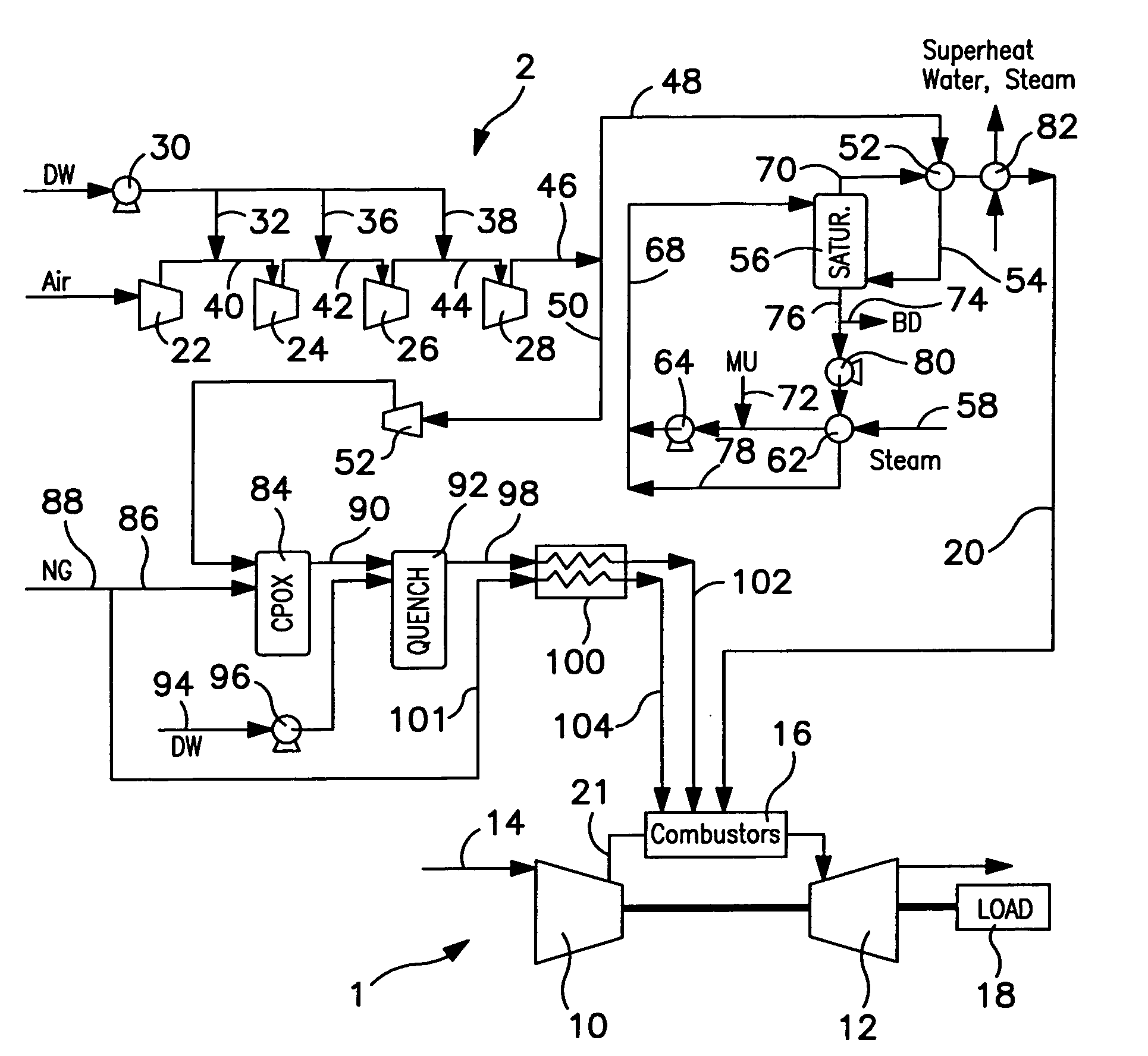
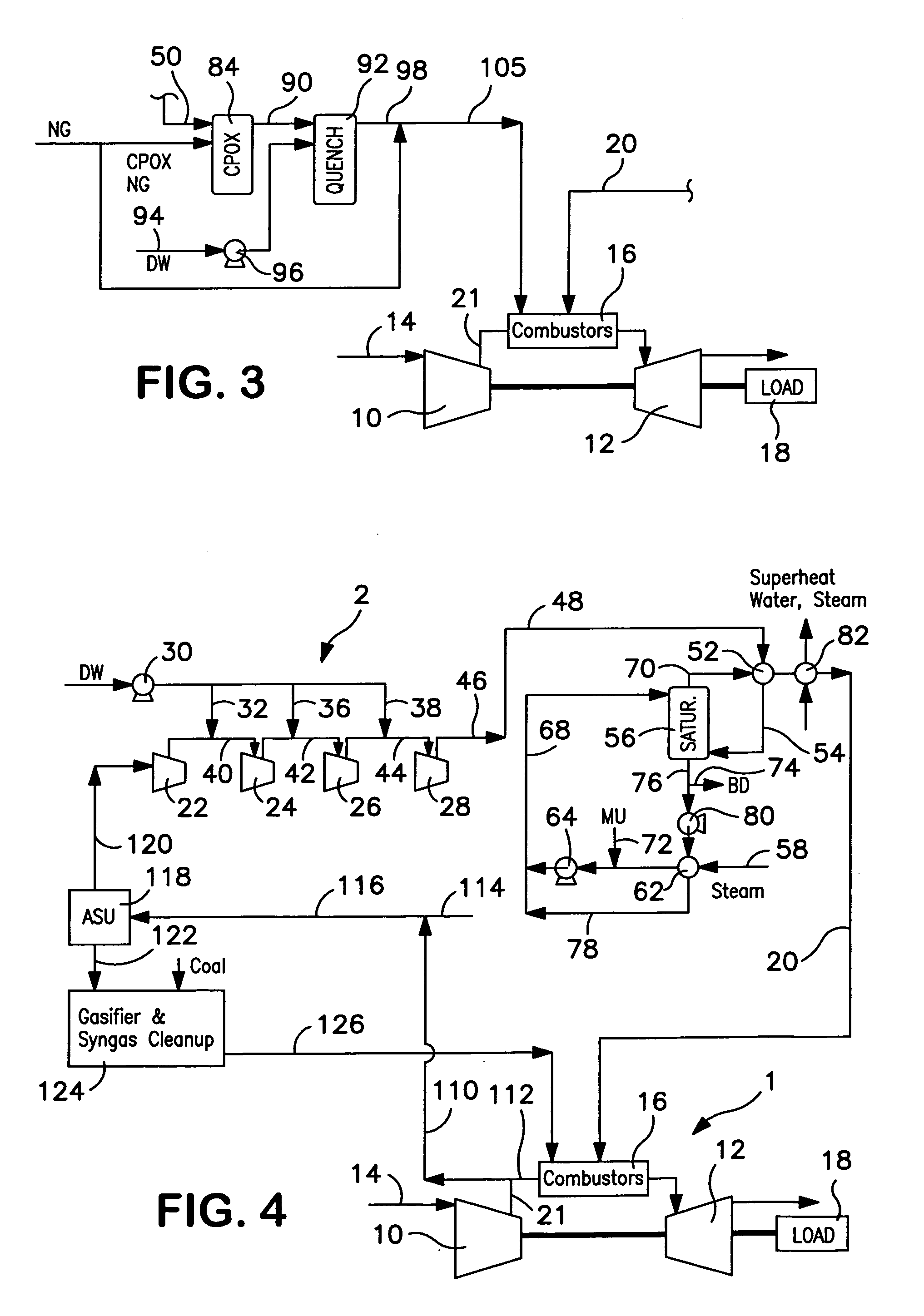
[0020]With reference to FIG. 1, the power of a gas turbine 1 is augmented by use of systems that will be hereafter described.

[0021]Gas turbine 1 is provided with a gas turbine compressor 10 that is coupled to gas turbine expander 12. It is understood that turbine compressor 10 and gas turbine expander 12 could have a number of intermediate stages. An air stream 14 is compressed in compressor 10 and then introduced into combustors 16 as a compressed air stream. Fuel is added to the combustors and the combustion occurring therewithin produces a heated stream that is introduced to gas turbine expander 12. Gas turbine compressor 10 and expander 12 are mechanically coupled and the excess energy is used to power a load 18 which can be an electrical generator.

[0022]The power of gas turbine 1 is augmented by a vapor containing compressed gas stream 20 produced by an auxiliary compressor that can be a water injected, intercooled air compressor train 2. The mass of vapor contained in compress...


PUM


Abstract

A power augmentation method for a gas turbine in which water is injected into one or more stages of an auxiliary compressor to produce a vapor containing gas stream. The vapor containing gas stream is at least in part introduced into combustors of the gas turbine for power augmentation. Part of the vapor containing compressed gas stream can be introduced into a reactor to generate a hydrogen containing synthesis gas to support lower flame temperatures occurring within the combustors of the gas turbine due to the introduction of the vapor containing gas stream. In such manner, NOx emissions of the gas turbine can be reduced. Furthermore, the power augmentation method can be conducted in conjunction with an integrated gasification combined cycle.

Description

FIELD OF THE INVENTION[0001]The present invention relates to a method for augmenting the power output of the gas turbine in which a water vapor containing compressed gas stream is introduced into the gas turbine combustor to increase the mass flow rate to the expander and therefore the power output of the gas turbine.BACKGROUND OF THE INVENTION[0002]Gas turbines are used in a variety of industrial settings to supply power to a load, generally an electrical generator. A gas turbine consists of a compressor to compress air and an expander to recover energy from the compressed air after having been heated. The compressed air is heated within a set of combustors located between the compressor and the expander by supporting combustion of a fuel introduced into the combustors.[0003]There are a variety of prior art examples in which the potential power output of a gas turbine is increased by water injection into the compressor, the combustor or both. Water injection into the compressor inc...

Claims


Application Information

Patent Timeline
Patent Type & Authority Patents(United States)
IPC IPC(8): F02C3/30
CPCC01B3/386F01K21/047F01K23/068F02C3/22F02C3/305C01B2203/0233C01B2203/0261C01B2203/06C01B2203/0877C01B2203/0883C01B2203/1241F05D2270/082Y02E20/18
Inventor DRNEVICH, RAYMOND FRANCISRAYBOLD, TROY MICHAEL
Owner PRAXAIR TECH INC
Why Eureka
Try Eureka