
Indirect variable valve actuation for an internal combustion engine

a technology of indirect variable valve actuation and internal combustion engine, which is applied in the direction of electric control, combustion-air/fuel-air treatment, instruments, etc., can solve the problems of costly and complicated camless valve actuation system, and achieve the effects of improving volumetric efficiency, simple, and low cos

Inactive Publication Date: 2006-11-21
RICARDO INC
View PDF61 Cites 5 Cited by
  • Summary
  • Abstract
  • Description
  • Claims
  • Application Information

AI Technical Summary

Benefits of technology

[0007]An engine system, according to this invention, provides the advantage of a simple, low-cost indirect variable valve actuation that allows for a large number of engine cycle-valve timing combinations for both full-load and partial-load performance. The engine reduces fuel consumption, improves volumetric efficiency, and improves engine emissions on a comparable basis with other engine induction systems. The system consists of flaps installed in series with conventional engine valves such that the flaps can control flow into or out of the cylinder during the period when the optimally profiled engine valve is allowing flow. This relieves the variable valve actuation device of the difficult task of sealing and enduring engine combustion temperatures and pressure, but still allows control of engine flows by the engine management system.
[0008]The engine intake flaps are controlled readily using relatively simple control logic and at low system cost compared to camless and variable valve actuation systems that accomplish similar functions. For pulse charging application of turbo-charged engines, this system can be used to reduce pumping losses compared to known resonance gas systems, and to improve engine air charging performance further.
[0010]For turbo-charged engines, intake resonance can be used in combination with the flaps to improve engine air charging by coordinating the operation of the flaps with that of the engine intake valves to trap intake air pressure pulses in the cylinder and preventing them from flowing from the cylinder back into a resonator. Such an engine system includes multiple engine cylinders having first and second intake ports, first intake runners providing passages through which intake gas enters the first intake port of each respective cylinder, and second intake runners providing passages through which intake gas enters the second intake port of each respective cylinder. Each cylinder includes first intake valves for opening and closing the first intake port of each respective cylinder, and second intake valves for opening and closing the second intake port of each respective cylinder. A plenum containing intake gas communicates with a first resonator connected to the first outlet and the first intake runner of each respective cylinder for producing in the first intake runner first pressure pulses of intake gas having a varying cyclic amplitude. The plenum also communicates with a second resonator connected to the second outlet and with the second intake runner of each respective cylinder for producing in the second intake runner second pressure pulses of intake gas having a varying cyclic amplitude that is out of phase with the first cyclic pressure pulses. Flaps, located in a first intake runner upstream from, and in series with a respective first intake valve, have first and second positional states that vary during each engine cycle. The first state opens the first intake runner passage to permit the pressure pulses to enter the cylinder through the intake port. The second state at least partially closes the first intake runner passage to limit or prevent intake gas from exiting the cylinder through the intake port.

Problems solved by technology

But these camless valve actuation systems are costly and complicated.
However, these long opening periods will be detrimental during other modes of engine operation, at lower speeds and loads, and thus require additional controls to provide variability which produces optimal performance at all points in the operating map.

Method used


Image

  • Indirect variable valve actuation for an internal combustion engine
  • Indirect variable valve actuation for an internal combustion engine
  • Indirect variable valve actuation for an internal combustion engine

Examples


Embodiment Construction

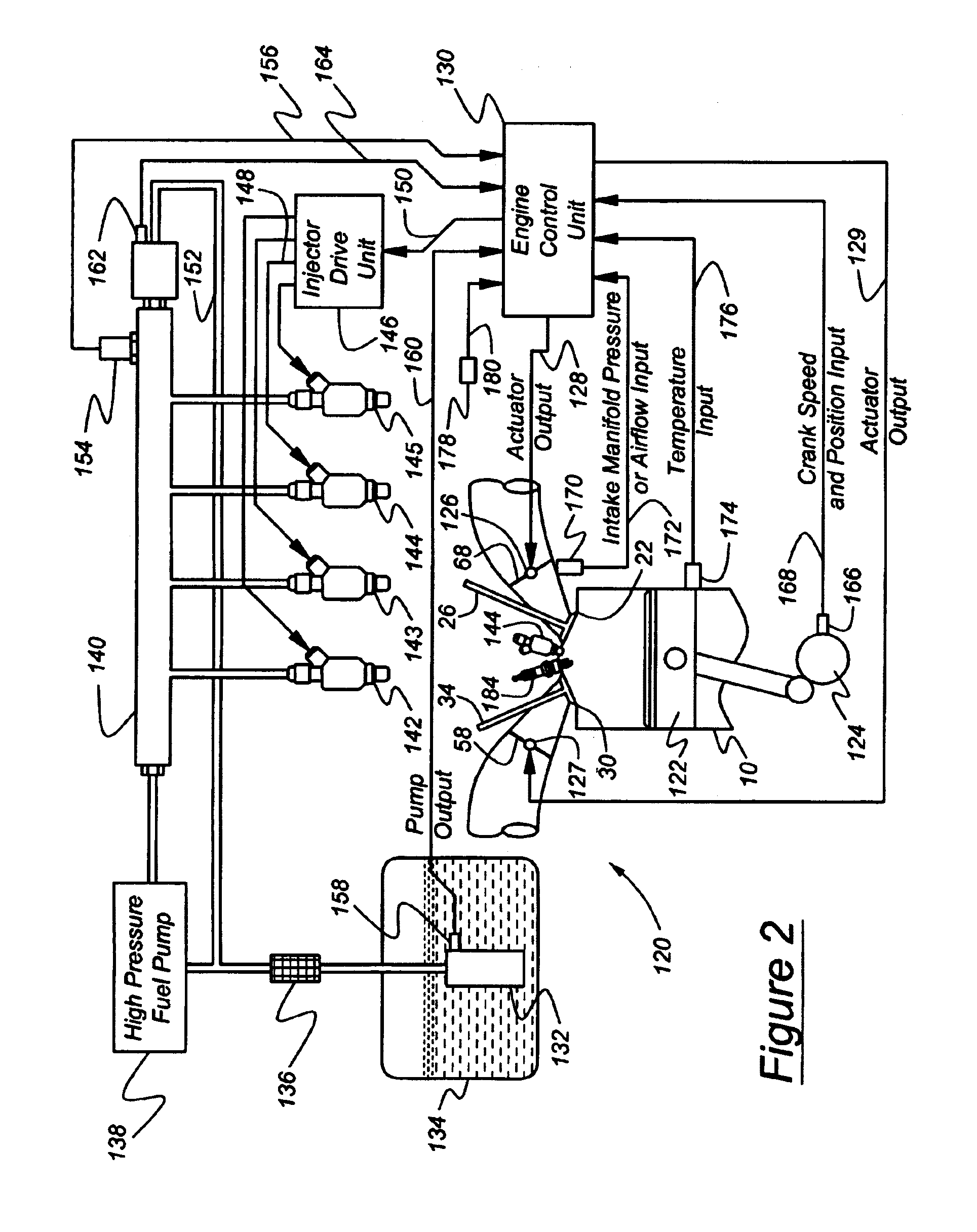
[0021]Although each cylinder of the engine described with reference in FIG. 1 has two intake ports and two exhaust ports, this invention can be applied to an engine having one intake port and one exhaust port per cylinder. For example, FIGS. 9, 10 and 11 illustrate the invention applied to engines having one intake port and one exhaust port. The engine described next with reference to FIG. 2 is another example of this invention applied to an engine having one intake port and one exhaust port per cylinder.

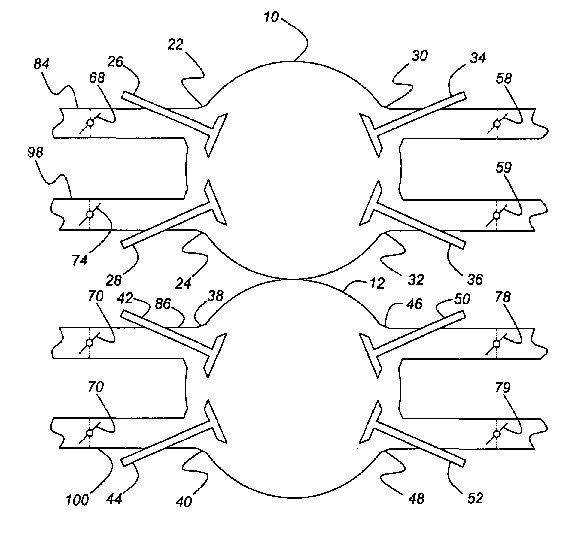
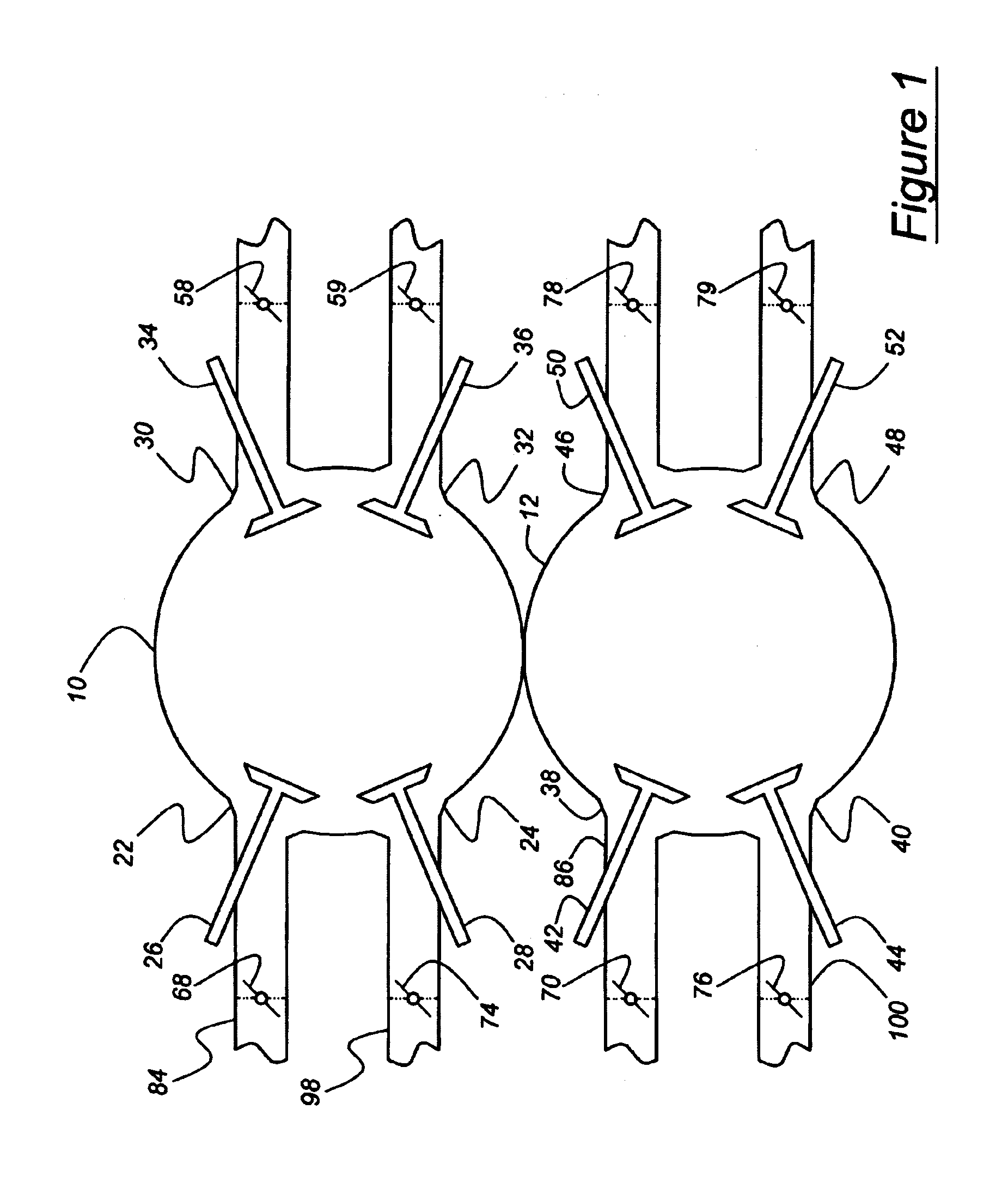
[0022]In FIG. 1 there is illustrated cylinder 10, 12 of an internal combustion engine, each cylinder containing a reciprocating piston (not shown) connected to a crankshaft. Each cylinder has two intake ports and two outlet ports. For example, cylinder 10 has intake ports 22, 24, which are opened and closed by intake valves 26, 28, respectively, and two outlet ports 30, 32, which are opened and closed by exhaust valves 34, 36, respectively. Camshafts to produce the conventional inta...


PUM


Abstract

A reciprocating piston-type internal combustion engine includes an engine cylinder, an intake port, an intake runner providing a passage through which intake gas enters the cylinder through the intake port, an intake valve for opening and closing the intake port, and a first flap located in the intake runner upstream from the intake valve, arranged in series with the intake valve, and having first and second positional states that vary during each engine cycle. The first state opens the intake runner passage to permit intake gas to enter the cylinder through the intake port. The second state at least partially closes the intake runner passage to control the flow of gas exiting or entering the cylinder through the intake port.

Description

BACKGROUND OF THE INVENTION[0001]The present invention relates generally to a variable intake control system for an internal combustion (IC) engine. More particularly, it pertains to an intake system that employs cycle-by-cycle control of airflow and compressible fluid resonance techniques to efficiently use or enhance intake gas pressure pulses when charging the cylinders.[0002]Camless variable valve actuation systems have been developed to control engine intake valves and exhaust valves using electrohydraulic and electromagnetic technology rather than conventional mechanical camshafts to provide variability in the charging process that cannot be obtained with fixed camshaft actuation of the engine valves. But these camless valve actuation systems are costly and complicated.[0003]Various techniques are used to improve the intake gas supply of reciprocating piston-type internal combustion engines. For example, U.S. Pat. No. 4,513,699 describes an intake gas resonance system associat...

Claims


Application Information

Patent Timeline
Patent Type & Authority Patents(United States)
IPC IPC(8): F02D11/10G01M19/00G01M99/00
CPCF02B29/083F02D9/04F02D41/0002F02D41/008F02M25/0752F02B27/008F02B27/0289F02M35/10045F02B23/101F02B29/0406F02B37/00F02B2075/125F02D13/0273F02D13/0284F02M25/0723Y02T10/146Y02T10/42F02M26/20F02M26/01Y02T10/12Y02T10/40
Inventor WAKEMAN, RUSSELL J.JACQUELIN, FREDERIC F.
Owner RICARDO INC
Learn More