Workpiece feeding apparatus

a feeding apparatus and workpiece technology, applied in conveyors, rope railways, ways, etc., can solve the problems of limited movement direction of hangers, low efficiency of conventional feeding apparatus for feeding workpieces, and difficulty in reaching working blocks, etc., to achieve simple mechanism for gripping wires, increase freedom of positioning transportation vehicles, and increase production efficiency

Inactive Publication Date: 2006-11-21
HONDA MOTOR CO LTD
View PDF36 Cites 17 Cited by
  • Summary
  • Abstract
  • Description
  • Claims
  • Application Information

AI Technical Summary

Benefits of technology

[0025]With the above arrangement, since the transportation vehicle is self-locked in the direction in which the wire moves, the mechanism for gripping the wire is made simple. As the wire can be gripped at any desired position, the freedom with which to position the transportation vehicle increases. The production efficiency is thus increased, and the structure of the workpiece feeding apparatus is simplified.
[0026]According to the present invention, a workpiece feeding apparatus has a workpiece transfer apparatus for transporting workpieces having different shapes between working blocks. The workpiece transfer apparatus comprises a plurality of positioning plates having space regions complementary to the profiles of the workpieces, respectively, and a drop prevention plate for preventing the workpieces from dropping off. The positioning plates are stacked upwardly in an increasing order of the space areas. The drop prevention plate is disposed beneath the lowest positioning plate.
[0027]With the above arrangement, even if the type of workpieces to be transported is changed, it is not necessary to use dedicated components, but all types of workpieces can stably be transported and reliably be positioned. As the workpiece feeding apparatus can handle workpieces having various shapes or positioned in various postures, the workpieces can easily be processed in a next process, and the freedom with which to use the workpiece feeding apparatus increases.

Problems solved by technology

With the above conventional workpiece feeding apparatus, however, the direction in which the hanger moves is limited by the position where the suspension support is mounted.
Specifically, the traveling direction of the hanger is one way only, and if the workpiece placed on the hanger has moved past a working block, then it is extremely difficult for the hanger to reach the working block again.
When such a situation occurs, the conventional workpiece feeding apparatus suffers a very low efficiency with which to feed workpieces.
If the workpiece is displaced for some reasons during its transportation, the workpiece may not be processed quickly and accurately.
If the workpiece is displaced a large distance, then it may possibly collide with the hanger or fall off the hanger.
However, the conventional arrangement is likely to suffer a substantial increase in the equipment cost.
However, the arm itself has a complex mechanism and needs electrical control for some actions to be made thereby.
Therefore, the arm is relatively complex in structure and highly costly.
Since the transportation vehicle itself has its own drive source, it is relatively heavy.
Consequently, the overall apparatus is highly expensive and needs to occupy an increased installation space.
Furthermore, if a certain transportation vehicle suffers a fault and stops moving in a certain working block, then since the transportation vehicle is of self-propelled type, it has to be repaired on site or removed from the track by some means because the faulty transportation vehicle, if left on the track, would obstruct the operation of other transportation vehicles.
When transportation vehicles suffer a failure, therefore, the machining conveyor apparatus tends to undergo a large drop in the operating efficiency.
Moreover, because the self-propelled transportation vehicles are heavy and cannot move at high speeds, the operating efficiency of the machining conveyor apparatus cannot be expected to be largely improved.
Consequently, design limitations are posed on working positions in that if the number of trolleys is to be increased to meet a demand for an increased operating efficiency, then the number of grip members on the trolley chain is unable to keep up with the increased number of trolleys, and the operating efficiency cannot be improved as desired.

Method used


Image

  • Workpiece feeding apparatus
  • Workpiece feeding apparatus
  • Workpiece feeding apparatus

Examples


Embodiment Construction

[0061]Workpiece feeding apparatus according to preferred embodiments of the present invention will be described in detail below with reference to the accompanying drawings.

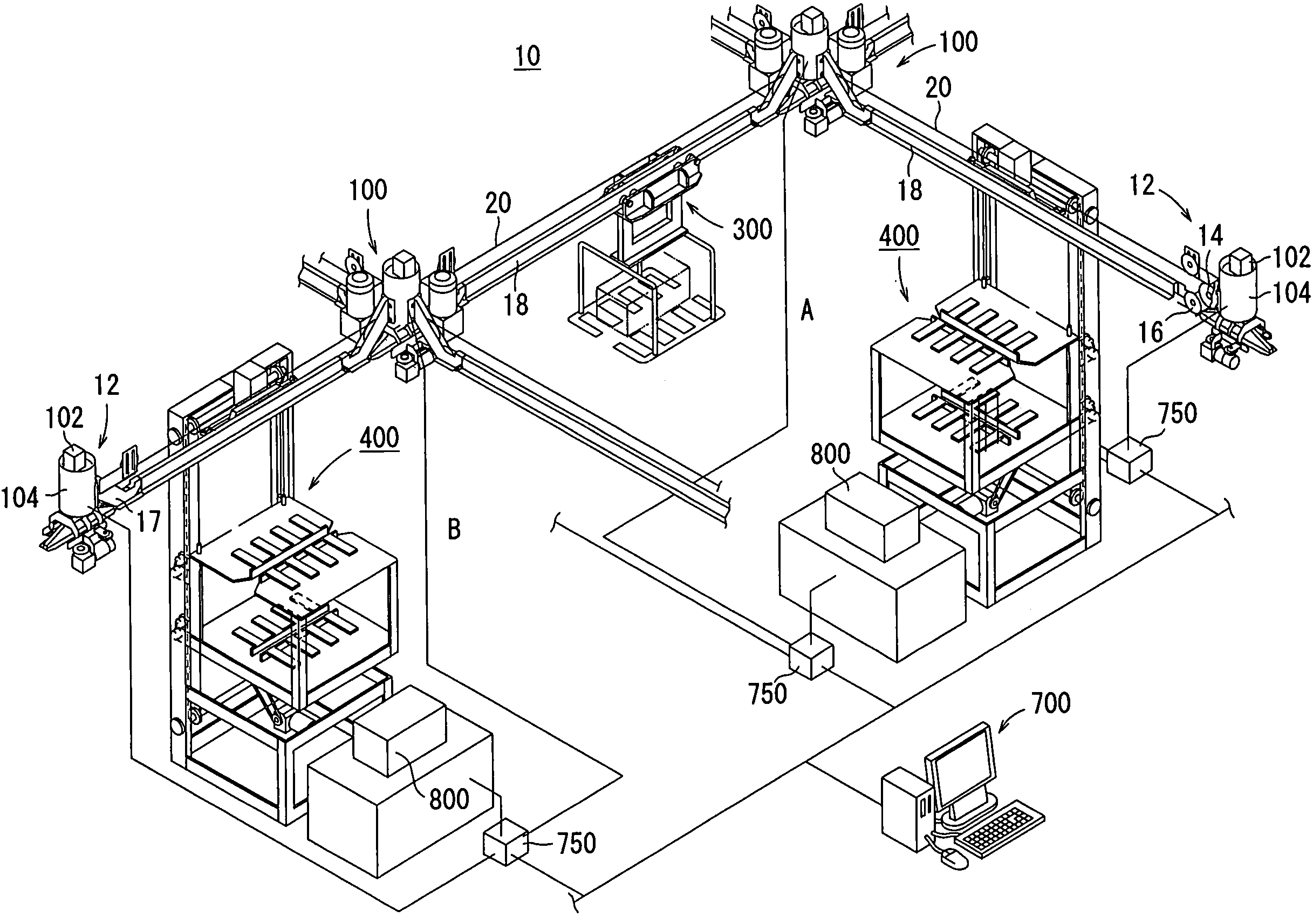
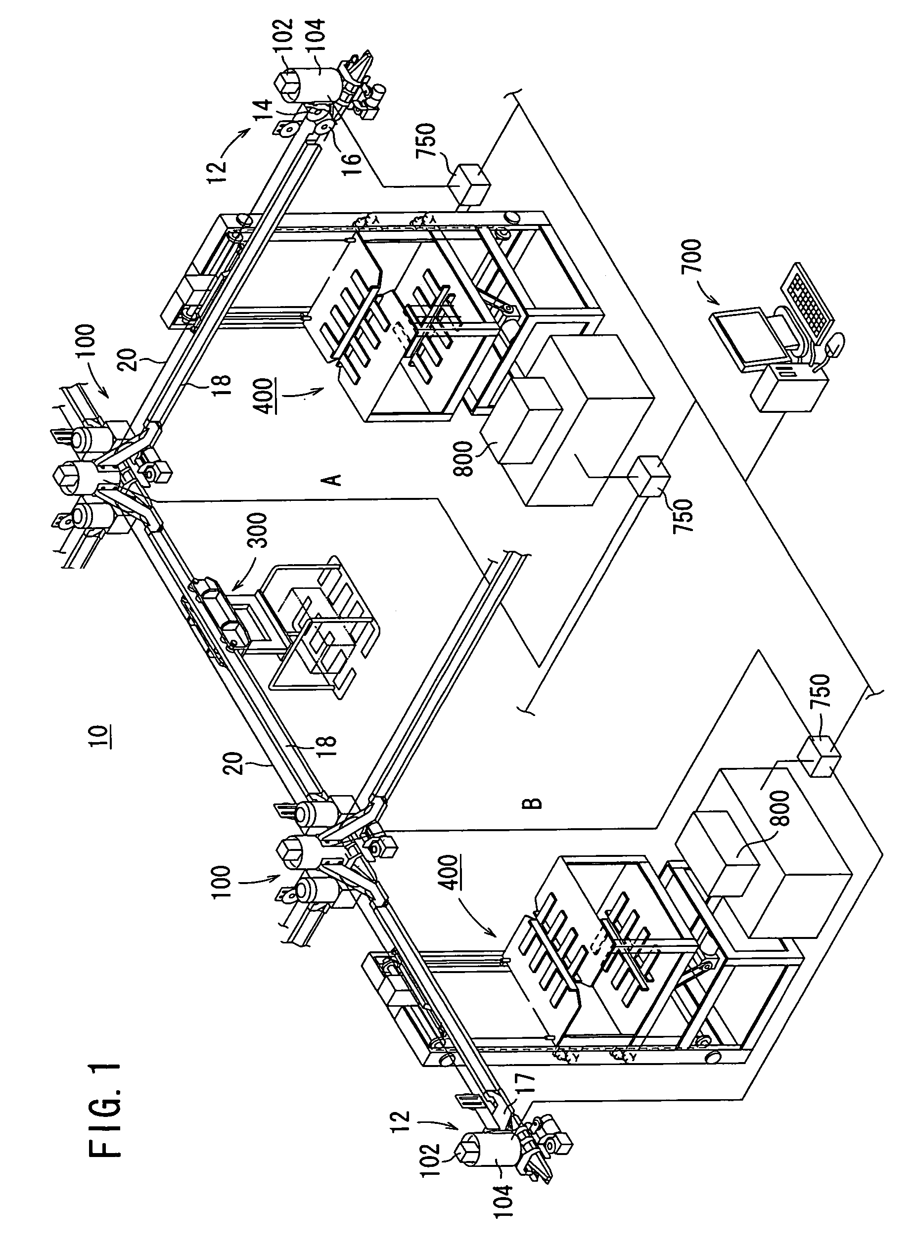
[0062]As shown in FIG. 1, a workpiece feeding apparatus 10 according to an embodiment of the present invention is basically disposed in a production system that is made up of a plurality of working blocks arranged in a crisscross pattern. The production system comprises a mechanical production system in which a workpiece that has been processed in one working block is moved by the workpiece feeding apparatus 10 to another working block where the workpiece is processed. For illustrative purposes, it is assumed that the production system according to the present embodiment has a working block A and a working block B.

[0063]As shown in FIG. 1, the working block A and the working block B are basically coupled to each other by rails. The working block A and the working block B have respective end transportation mechanis...


PUM


Abstract

A plurality of working blocks (A, B) are connected by rails (18). A branched transporting mechanism (100) is disposed at the intersections of the rails (18). A transportation vehicle (300) of non-self-propelled type moves on the rails (18) by the driving power of a wire (20). A placement table (450) is positioned in the vicinity of the working blocks (A, B). The placement table (450) moves up and down with a workpiece placed thereon between the transportation vehicle (300) and the working blocks (A, B). Transfer of work is effected by moving the placement table (450) up and down, and adjusting the height of the placement table (450) to the height of the transportation vehicle (300) or to the height of the working blocks (A, B). Further, the transportation vehicle (300) has a wire gripping mechanism (350) for gripping the wire (20), and workpiece placement plates (326a, 326b) for placing the workpiece thereon.

Description

TECHNICAL FIELD[0001]The present invention relates to a workpiece feeding apparatus for feeding workpieces between a plurality of working blocks.BACKGROUND ART[0002]There have been known workpiece feeding apparatus for feeding workpieces between a plurality of working blocks. For example, as disclosed in Japanese laid-open patent publication No. 59-69313, a typical known workpiece feeding apparatus has a hanger suspended from a trolley conveyor and having a suspension support disposed in a traveling direction of the hanger, a vertically movable unit that is vertically movable in response to a signal output from the hanger, and a conveyor positioned on an upper portion of the vertically movable unit for passing through the hanger and comprising a plurality of rotatable rollers. A workpiece placed on the hanger can be transferred to the conveyor.[0003]With the above conventional workpiece feeding apparatus, however, the direction in which the hanger moves is limited by the position wh...

Claims


Application Information

Patent Timeline
Patent Type & Authority Patents(United States)
IPC IPC(8): B61B3/00B61J1/06B25J5/02B65G17/20B65G35/06B65G47/61B65G47/90
CPCB65G35/06B65G47/901B65G2201/02
Inventor KOMATSU, TETSUHARUMUKUMOTO, TAKAJIKANBAYASHI, SATOSHINAKANO, JUNICHIMATSUNAGA, NAOYA
Owner HONDA MOTOR CO LTD
Why Eureka
Try Eureka