
Topologies for multiple energy sources

a technology of energy sources and topologies, applied in emergency power supply arrangements, process and machine control, instruments, etc., can solve the problems of inability to meet the electrical characteristics of an available electrical power source, inability to have a short-term response as suitable, and incompatible electrical requirements of a load

Active Publication Date: 2006-11-21
VIRGINIA TECH INTPROP INC
View PDF15 Cites 70 Cited by
  • Summary
  • Abstract
  • Description
  • Claims
  • Application Information

AI Technical Summary

Problems solved by technology

Often, the electrical requirements of a load are incompatible with the electrical characteristics of an available electrical power source.
Those skilled in the art will appreciate that certain types of DC power sources, such as fuel cells, are relatively good at supplying steady output power, but may not have as suitable a short term response.

Method used


Image

  • Topologies for multiple energy sources
  • Topologies for multiple energy sources
  • Topologies for multiple energy sources

Examples


Embodiment Construction

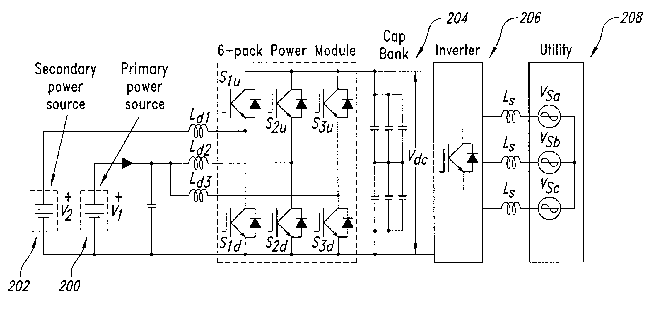
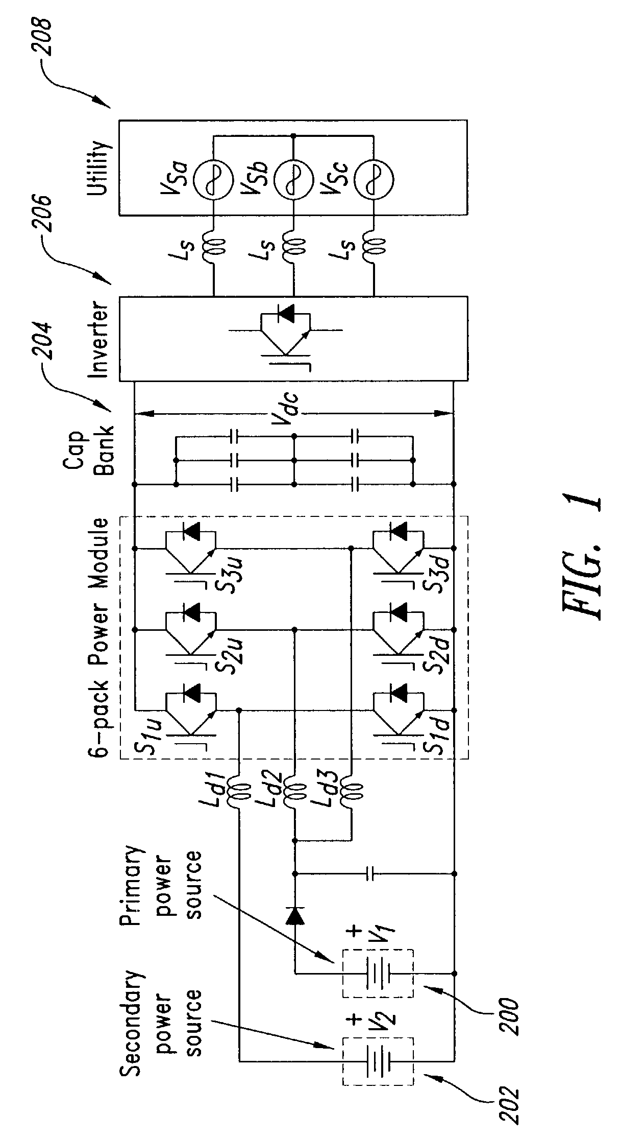
[0026]FIG. 1 illustrates a related-art circuit configuration. A primary power source 200 (e.g., a fuel cell) having voltage V1, and a secondary power source 202 (e.g., a battery) having voltage V2 supply the power. Other examples of primary power source 200 include photovoltaic power sources, biomass power sources, geothermal power sources, etc. Other examples of secondary power source 202 include inertial devices or ultra capacitors. The output voltage Vdc across capacitor bank 204 supplies a three-phase inverter 206, which inverts the DC input power to AC output power, and supplies the AC output power to a load such as a utility 208. In other applications, the voltage Vdc can supply a DC load (not shown) or an inverter with any phase numbers such as single-phase and four-phase inverters (not shown).

[0027]Inductor Ld1, and switch-diode pairs S1u and S1d, serve as a bi-directional dc—dc converter. With S1u, inductor Ld1, and the anti-paralleled diode of S1d, the circuit serves as a ...


PUM


Abstract

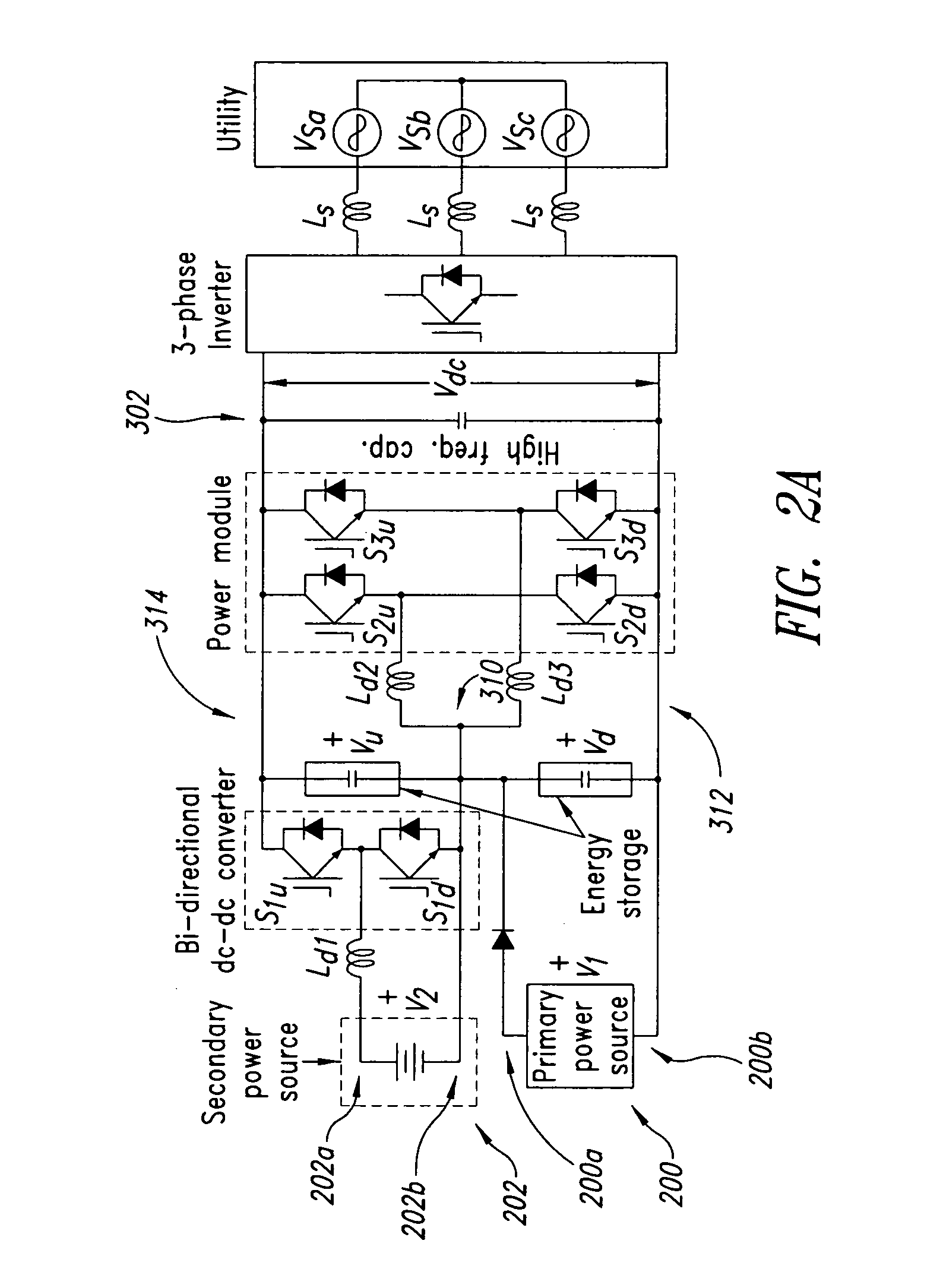
A system and method for converting power are disclosed. Briefly described, one embodiment comprises a first power source having a first-source positive terminal and a first-source negative terminal; a second power source having a second-source positive terminal and a second-source negative terminal; an output capacitor having an output-capacitor positive terminal operably coupled with the second-source positive terminal and an output-capacitor negative terminal operably coupled with the first-source negative terminal; a series electrical connection between the first-source positive terminal and the second-source negative terminal; a boost converter having a boost-converter input operably coupled with the series electrical connection and the first-source negative terminal, and a boost-converter output operably coupled with the output-capacitor positive and negative terminals; and a buck-boost converter having a buck-boost-converter input operably coupled with the series electrical connection and the second-source positive terminal, and a buck-boost-converter output operably coupled with the output-capacitor positive and negative terminals.

Description

BACKGROUND OF THE INVENTION[0001]1. Field of the Invention[0002]The present invention relates, in general, to electric power supplies employing either or both DC—DC power converters and DC-AC power inverters.[0003]2. Description of the Related Art[0004]Often, the electrical requirements of a load are incompatible with the electrical characteristics of an available electrical power source. For example, the voltage of the load may be incompatible with the voltage of the power source (e.g., a 24 volt load and a 12 volt source), or the current type of the power source may be incompatible with the current type of the load (e.g., an AC load and a DC source or a DC load and an AC source). In such situations, an electric power supply may remedy the incompatibility.[0005]An electric power supply is a “translation” circuit that typically provides power with the characteristics required by the load from an electric power source with characteristics which may be incompatible with the characteri...

Claims


Application Information

Patent Timeline
Patent Type & Authority Patents(United States)
IPC IPC(8): H02J1/00H02M3/158H02M7/5387
CPCH02J9/062H02M3/1582H02M7/5387H02M2001/0074H02M1/0074
Inventor LAI, JIH-SHENG
Owner VIRGINIA TECH INTPROP INC
Learn More