Receiver in a radio communication system

a radio communication system and receiver technology, applied in the field of receivers in radio communication systems, can solve the problems of lower response speed of phase locked loop, increasing circuit scale and power consumption, etc., and achieve low spurious level and high frequency precision without increasing power consumption of a dsp-based signal generator.

Inactive Publication Date: 2006-11-21
SAMSUNG ELECTRONICS CO LTD
View PDF14 Cites 18 Cited by
  • Summary
  • Abstract
  • Description
  • Claims
  • Application Information

AI Technical Summary

Benefits of technology

[0010]It is, therefore, an object of the present invention to provide a receiver having a low spurious l

Problems solved by technology

However, it is known that a reduction in bandwidth of a DDS-driven phase locked loop such as the phase locked loop 102 desirably narrows a band where the spurious signals are not suppressed, but undesirably lowers a response speed of the phase locked loop.
However, the above listed attempts to reduce the spurious signal (1) cause an increase in circuit scale and power consumption, (2) also cause an increase in circuit scale and power consumption, though less

Method used


Image

  • Receiver in a radio communication system
  • Receiver in a radio communication system
  • Receiver in a radio communication system

Examples


Embodiment Construction

[0026]A preferred embodiment of the present invention will be described herein below with reference to the accompanying drawings. In the following description, well-known functions or constructions are not described in detail since they would obscure the invention in unnecessary detail.

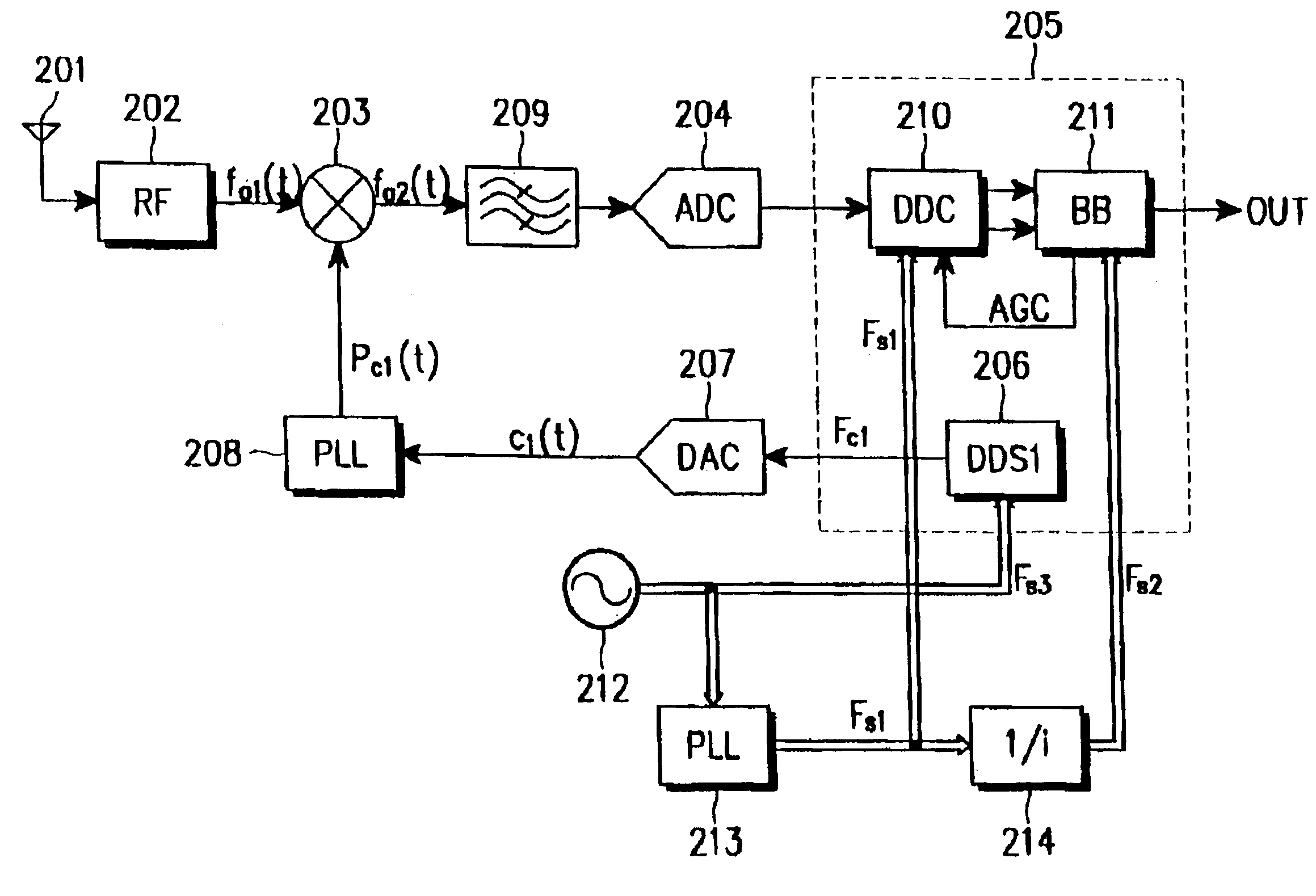
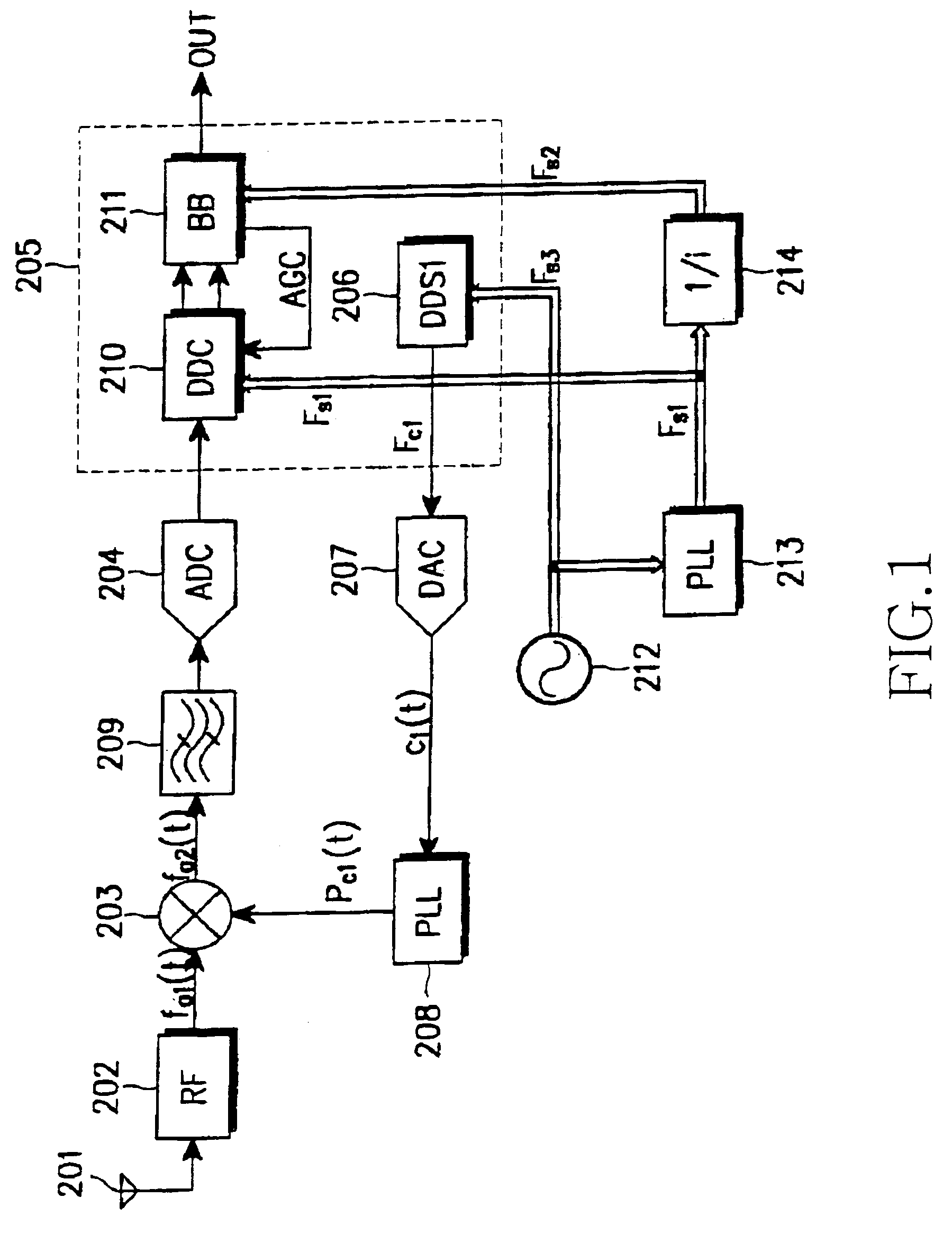
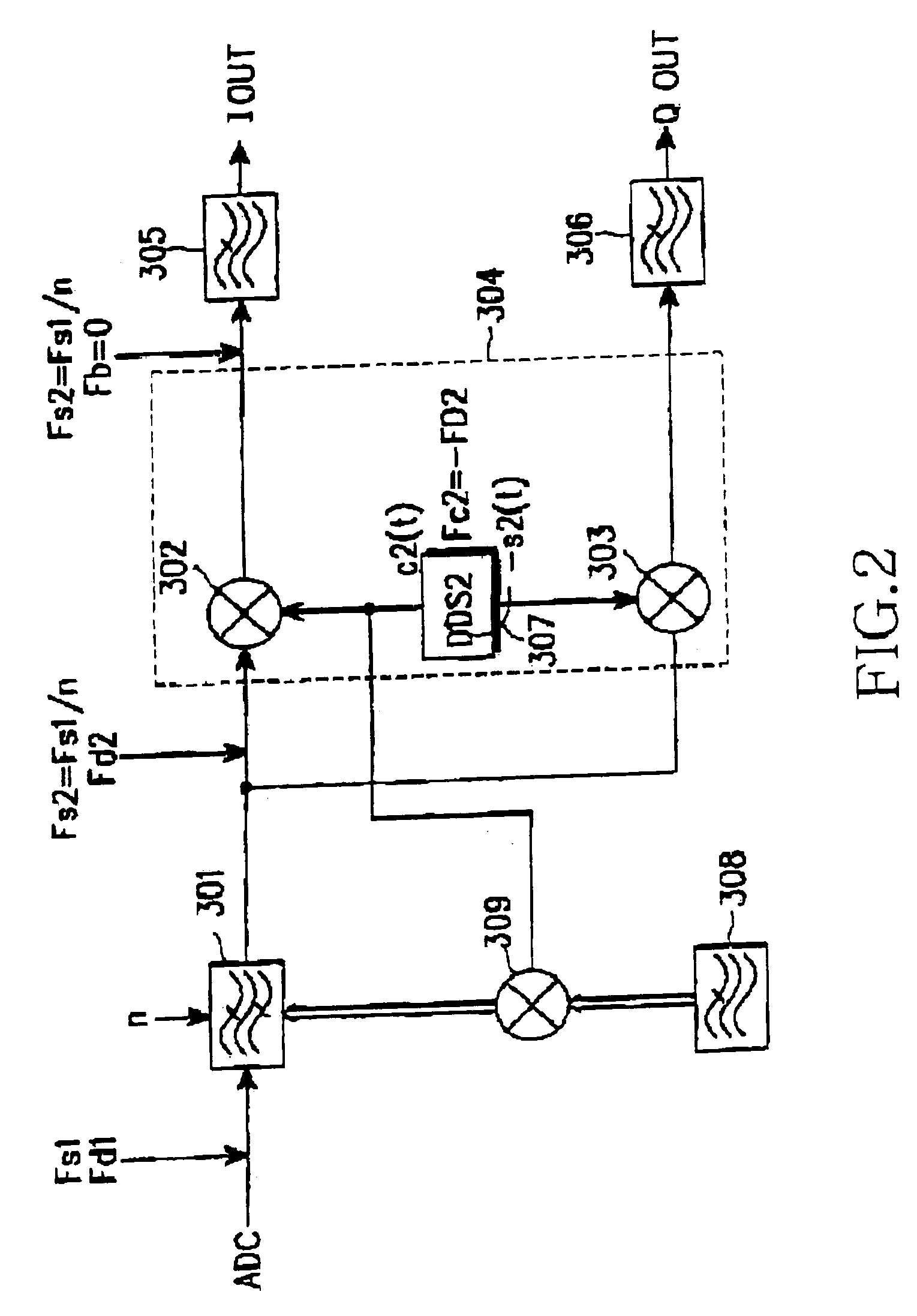
[0027]FIG. 1 illustrates a receiver according to an embodiment of the present invention, and FIG. 2 illustrates a detailed structure of the digital down-converter (DDC) 210 shown in FIG. 1.

[0028]Referring to FIGS. 1 and 2, an input signal fa1(t) received through an antenna 201 is provided to a first mixer 203 through an RF unit 202. The first mixer 203 multiplies the input signal fa1(t) from the RF unit 202 by a local signal pc1(t) provided from a phase locked loop (PLL) 208 to convert the input signal fa1(t) to an IF signal fa2(t), and provides the converted IF signal fa2(t) to an analog-to-digital converter (ADC) 204 through a bandpass filter (BPF) 209. The local signal pc1(t) is an output signal of...


PUM


Abstract

A receiver has a low spurious level and a high frequency precision without increasing power consumption of a local oscillator. The receiver comprises first and second local oscillators; a phase locked loop operating based on an output of the first local oscillator; a first mixer for receiving an RF signal or an IF signal, and converting the received signal to a second IF signal according to an output signal of the phase locked loop; an analog-to-digital converter for converting an output signal of the first mixer to a digital signal; a second mixer for converting the digital signal to a detection process frequency according to an output of the second local oscillator; and a filter for bandpass filtering, interposed between the first mixer and the analog-to-digital converter or between the analog-to-digital converter and the second mixer.

Description

PRIORITY[0001]This application claims priority to an application entitled “Receiver” filed in the Japanese Patent Office on Sep. 21, 2000 and assigned Ser. No. 2000-287667, the contents of which are hereby incorporated by reference.BACKGROUND OF THE INVENTION[0002]1. Field of the Invention[0003]The present invention relates generally to a receiver in a radio communication system, and in particular, to a receiver for sampling an intermediate frequency (IF) signal and then performing digital signal processing on the sampled signal.[0004]2. Description of the Related Art[0005]A conventional receiver samples a received signal and performs digital signal processing on the sampled signal in an RF (Radio Frequency) unit or an IF unit, for signal selection or detection. A block diagram of the conventional receiver is illustrated in FIG. 4.[0006]Referring to FIG. 4, a phase locked loop (PLL) 102 outputs a local signal depending on a reference signal, the reference signal being an output sign...

Claims


Application Information

Patent Timeline
IPC IPC(8): H04L27/06H03H17/00H03B28/00H03D3/00H03D7/16H04B1/26
CPCH03D3/007H03D7/165H04B1/26
Inventor TAKAHIKO, KISHI
Owner SAMSUNG ELECTRONICS CO LTD
Why Eureka
Try Eureka