Gas injection for uniform composition reactively sputter-deposited thin films

a technology of uniform composition and reactive sputtering, which is applied in the direction of electrolysis components, vacuum evaporation coatings, coatings, etc., can solve the problems of poor suited to the high film uniformity requirements of the hard disk industry, and achieve the effect of improving the reactive sputtering apparatus and improving the sputtering apparatus

Inactive Publication Date: 2006-11-28
SEAGATE TECH LLC
View PDF10 Cites 4 Cited by
  • Summary
  • Abstract
  • Description
  • Claims
  • Application Information

AI Technical Summary

Benefits of technology

[0013]Another advantage of the present invention is an improved reactive sputtering apparatus.
[0014]Still another advantage of the present invention is an improved apparatus for reactive sputtering of magnetic thin films for magnetic recording media.
[0015]A further advantage of the present invention is an improved method of forming a thin film by sputtering.
[0016]Yet another advantage of the present invention is an improved method of forming a thin film by reactive sputtering.
[0017]A still further advantage of the present invention is an improved method of forming magnetic thin films for magnetic recording media by reactive sputtering.
[0018]Further advantages of the present invention include improved magnetic recording media comprising reactively sputtered magnetic thin films with improved compositional uniformity.

Problems solved by technology

), typically employ gas injection means with design criteria, e.g., geometries, which are poorly suited to the high film uniformity requirements of the hard disk industry, particularly with respect to the special problems presented by reactive sputtering in atmospheres containing O2.

Method used


Image

  • Gas injection for uniform composition reactively sputter-deposited thin films
  • Gas injection for uniform composition reactively sputter-deposited thin films
  • Gas injection for uniform composition reactively sputter-deposited thin films

Examples


Embodiment Construction

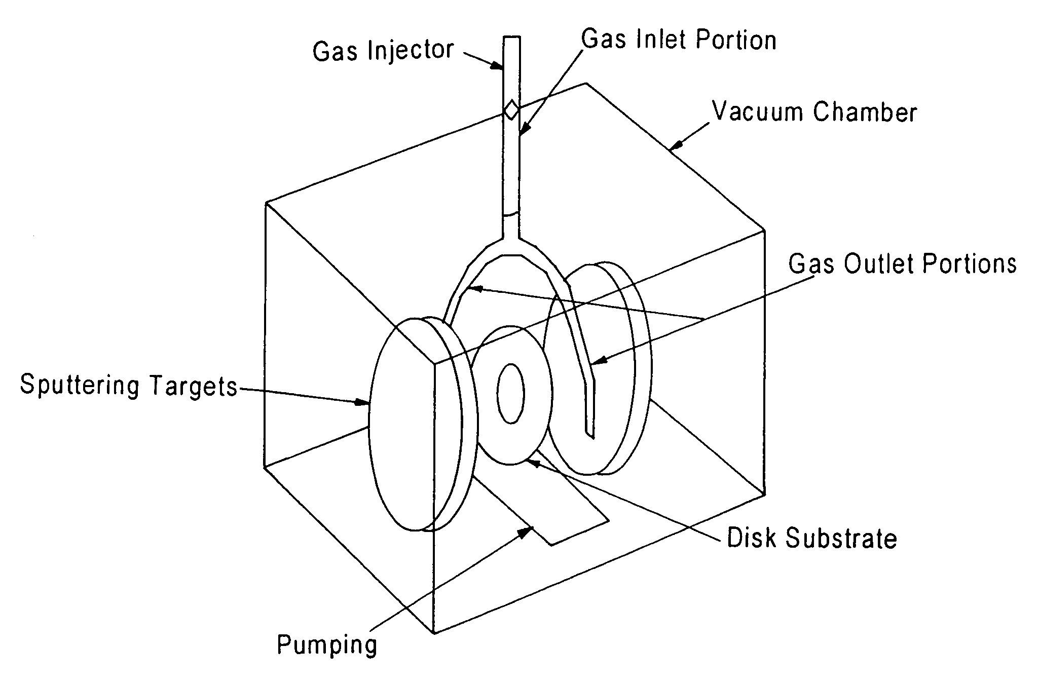
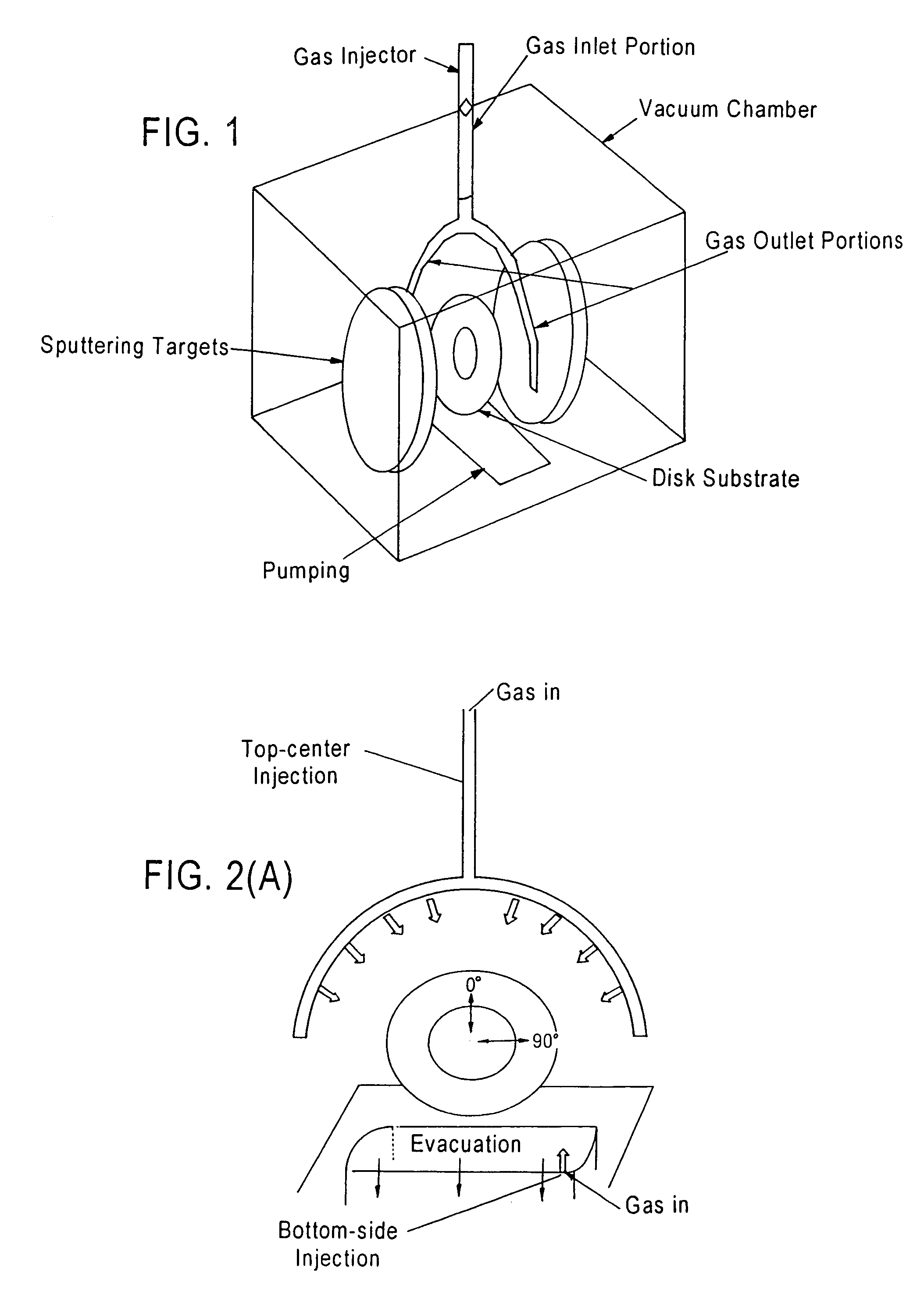
[0069]The present invention is based upon recognition by the inventors that reactive sputter deposition apparatus may be provided with appropriately designed gas injecting means for readily and reliably forming reactively sputtered thin films having a uniform composition, i.e., content of at least one film component supplied by the reactive gas, over the entire substrate / workpiece surface, e.g., 360° in the case of disk-shaped substrates / workpieces. According to the invention, reactive sputtering apparatus equipped with gas injector means including a gradient orifice array is provided for achieving substantially equal reactive gas injection rates along the length of a gas distribution manifold which is fed with gas from one end. Proper optimization of the orifice size distribution allows the downstream orifices of the manifold to be arbitrarily large, thereby enabling rapid vacuum chamber fill and pump-out essential for short cycle times. Advantageously, the design of the gradient o...


PUM

PropertyMeasurementUnit
diameteraaaaaaaaaa
wall thicknessaaaaaaaaaa
pressureaaaaaaaaaa

Abstract

A method of forming a thin film on a substrate / workpiece by sputtering, comprising steps of:(a) providing an apparatus comprising a vacuum chamber including at least one sputtering source and a gas supply means for injecting a gas containing at least one reactive component into said chamber, the gas supply means comprising a plurality of differently-sized outlet orifices adapted for providing substantially the same flow rate of gas from each orifice;(b) providing a substrate / workpiece having at least one surface for formation of a thin film thereon;(c) generating a sputtered particle flux from the at least one sputtering source;(d) injecting the gas containing the at least one reactive component into the chamber via the gas supply means, such that the same gas flow rate is provided at each orifice; and(e) forming a reactively sputtered thin film on the at least one surface of the substrate / workpiece, the reactively sputtered thin film having a substantially uniform content of the at least one reactive component.

Description

FIELD OF THE INVENTION[0001]The present invention relates to a method and apparatus for injection of a gas into a sputtering apparatus chamber for obtaining highly uniform composition reactive sputter deposition of a thin film over substantially the entirety of a substrate surface. The invention has particular utility in the manufacture of disk-shaped magnetic and magneto-optical data / information storage and retrieval media.BACKGROUND OF THE INVENTION[0002]Magnetic and MO recording media are widely employed in various applications, particularly in the computer industry for data / information storage and retrieval purposes. A magnetic medium in, e.g., disk form, such as utilized in computer-related applications, comprises a non-magnetic substrate, for example, of glass, ceramic, glass-ceramic composite, polymer, metal or metal alloy, typically an aluminum (Al)-based alloy such as aluminum-magnesium (Al—Mg), having at least one major surface on which a layer stack comprising a plurality...

Claims


Application Information

Patent Timeline
Patent Type & Authority Patents(United States)
IPC IPC(8): C23C14/34C23C14/00C23C14/32
CPCC23C14/0063C23C14/3464H01J37/3244
Inventor BRUCKER, CHARLES FREDERICKMCLEOD, PAUL S.YI, CHANG
Owner SEAGATE TECH LLC
Why Eureka
Try Eureka