Fuel cell

a fuel cell and solid-state technology, applied in the field of solid-state polymer fuel cells, can solve the problems of increasing danger, insufficient air supplied to the cathode catalyst layer, and inability to smoothly effected reaction in the cathode 104/b>, and achieve the effect of high reliability

Inactive Publication Date: 2006-11-28
MITSUBISHI ELECTRIC CORP
View PDF12 Cites 12 Cited by
  • Summary
  • Abstract
  • Description
  • Claims
  • Application Information

AI Technical Summary

Benefits of technology

[0018]Therefore, with the foregoing in mind, it is an object of the present invention to provide a highly reliable fuel cell in which accumulation of water in a cathode and drying in an anode are prevented, a change in composition of fuel can be addressed, and an electrolyte membrane is unlikely to be damaged.

Problems solved by technology

Therefore, sufficient air is not supplied to the cathode catalyst layer 107, and the reaction in the cathode 104 is not smoothly effected.
When the electrolyte membrane 102 becomes thin, there arises a problem of increasing the danger that the electrolyte membrane 102 is damaged.
Therefore, in the case where hydrogen containing no carbon monoxide is used as fuel, it is not appropriate to use a catalyst containing a large amount of ruthenium as a metal catalyst.
Thus, the composition of an appropriate metal catalyst is varied depending upon the composition of fuel, resulting in a problem in that the anode catalyst layer 105 cannot have sufficient performance, except for the case where a metal catalyst is used for the anode catalyst layer 105, and fuel allowing the metal catalyst to exhibit its function as a catalyst is supplied.

Method used


Image

  • Fuel cell
  • Fuel cell
  • Fuel cell

Examples


embodiment 1

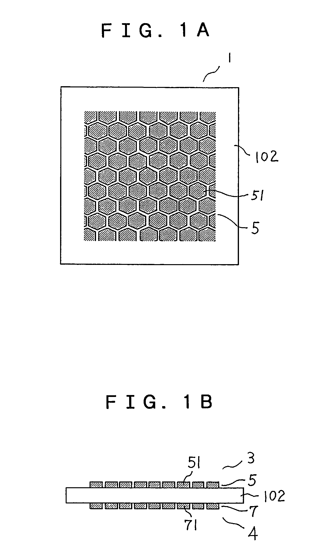
[0031]FIGS. 1A and 1B are a top view and a side view, respectively, schematically showing a structure of main portions of a fuel cell of Embodiment 1 according to the present invention. In FIGS. 1A and 1B, a fuel cell 1 includes an electrolyte membrane 102, an anode 3 (corresponding to the anode 103 in FIG. 8) that is in contact with one surface of the electrolyte membrane 102, and a cathode 4 (corresponding to the cathode 104 in FIG. 8) that is in contact with the other surface of the electrolyte membrane 102. The anode 3 includes an anode catalyst layer 5 applied to the electrolyte membrane 102, and a fuel-side gas diffusion layer 106 overlapped with the anode catalyst layer 5. The cathode 4 includes a cathode catalyst layer 7 applied to the electrolyte membrane 102, and an air-side gas diffusion layer 108 overlapped with the cathode catalyst layer 7.

[0032]The anode catalyst layer 5 has a plurality of divided catalyst segments 51. The shape of each of the divided catalyst segments...

embodiment 2

[0041]FIGS. 3A to 3C are views schematically showing a structure of main portions of a fuel cell in accordance with Embodiment 2 of the present invention. FIG. 3A is a front view seen from an anode side. FIG. 3B is a front view thereof seen from a cathode side. FIG. 3C is a side view thereof. In FIGS. 3A to 3C, a fuel cell 1 includes an electrolyte membrane 102, an anode 3 that is in contact with one surface of the electrolyte membrane 102, and a cathode 4 that is in contact with the other surface of the electrolyte membrane 102. The anode 3 includes an anode catalyst layer 5 applied to the electrolyte membrane 102, and a fuel-side gas diffusion layer 106 overlapped with the anode catalyst layer 5. The cathode 4 includes a cathode catalyst layer 7 applied to the electrolyte membrane 102, and the air-side gas diffusion layer 108 overlapped with the cathode catalyst layer 7.

[0042]The anode catalyst layer 5 includes hydrophilic divided catalyst segments 52a and water-repellent divided ...

embodiment 3

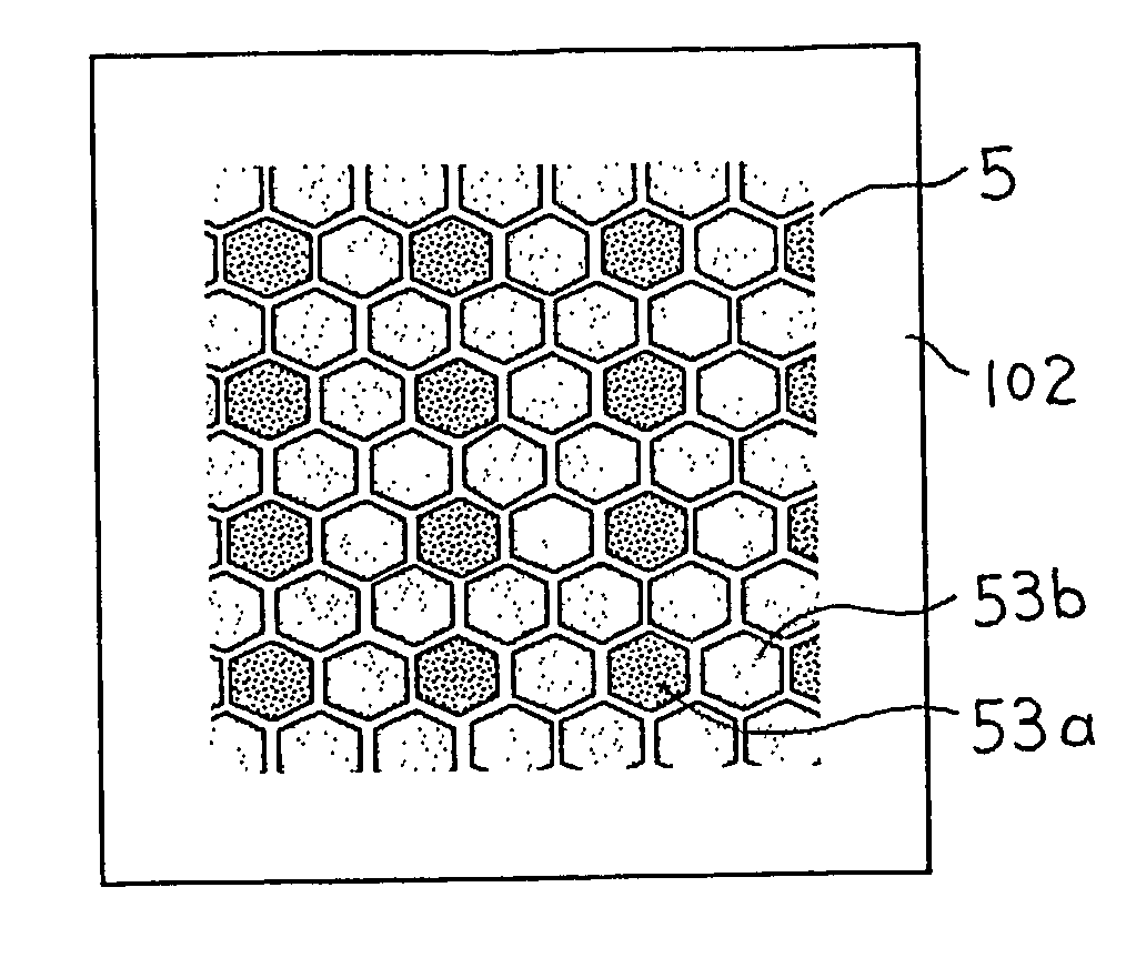
[0050]FIGS. 4A and 4B are views schematically showing a structure of main portions of a fuel cell in accordance with Embodiment 3 of the present invention. FIG. 4A is a front view seen from an anode side. FIG. 4B is a side view thereof. In FIGS. 4A and 4B, an anode catalyst layer 5 includes divided catalyst segments 53a and divided catalyst segments 53b, which have different compositions of a metal catalyst. In the divided catalyst segments 53a, a platinum-ruthenium alloy (atomic ratio between platinum and ruthenium=2:1) is used as a metallic catalyst. In the divided catalyst segments 53b, a platinum-ruthenium alloy (atomic ratio between platinum and ruthenium=1:2) is used as a metal catalyst. Furthermore, herein, the total area of the divided catalyst segments 53a is three times that of the divided catalyst segments 53b. The shape of each of the divided catalyst segments 53a and 53b or the gaps therebetween are the same as those in Embodiment 1, and the remaining structure is also ...


PUM

PropertyMeasurementUnit
current densityaaaaaaaaaa
widthaaaaaaaaaa
areaaaaaaaaaaa

Abstract

A fuel cell includes an electrolyte membrane, an anode on one surface of the electrolyte membrane and having an anode catalyst layer that is supplied with fuel and contains a platinum-ruthenium alloy catalyst, and a cathode on the other surface of the electrolyte membrane and having an cathode catalyst layer that is supplied with air and contains a platinum catalyst. The anode catalyst layer and the cathode catalyst layer include divided catalyst segments, and gaps between the divided catalyst segments that are adjacent to each other.

Description

CROSS REFERENCE TO RELATED APPLICATION[0001]This application is based on Application No. 2001-263484, filed in Japan on Aug. 31, 2001, the contents of which are hereby incorporated by reference.BACKGROUND OF THE INVENTION[0002]1. Field of the Invention[0003]The present invention relates to a fuel cell, and more particularly, to a solid polymer type fuel cell.[0004]2. Description of the Related Art[0005]A fuel cell has a pair of electrodes communicating via an electrolyte. One of the electrodes is supplied with fuel and the other is supplied with an oxidant for electrochemically reacting with the fuel, whereby chemical energy is directly converted to electric energy. More specifically, hydrogen gas that is fuel for a fuel cell is supplied to one electrode (anode), and oxygen that is an oxidant is supplied to the other electrode (cathode) so as to effect a reaction represented by the following Chemical Formulae (1) and (2) in the respective electrodes, whereby an electromotive force i...

Claims


Application Information

Patent Timeline
Patent Type & Authority Patents(United States)
IPC IPC(8): H01M4/86H01M4/90H01M4/88H01M4/92H01M4/96H01M8/10
CPCH01M4/8605H01M4/881H01M4/8846H01M4/8885H01M4/921H01M4/96H01M8/1004Y02E60/521Y02E60/50
Inventor FUKUMOTO, HISATOSHIHIROI, OSAMUMITSUDA, KENROMAEDA, HIDEOYOSHIDA, YASUHIROHAYASHI, TATSUYAYOSHIMURA, AKIHISA
Owner MITSUBISHI ELECTRIC CORP
Why Eureka
Try Eureka