Voltage regulator

a voltage regulator and voltage regulator technology, applied in the direction of electric variable regulation, process and machine control, instruments, etc., can solve the problems of inability to keep output voltage vout constant, and the amount of current which can be caused to flow when a load is heavy, so as to reduce the leakage current

Active Publication Date: 2006-11-28
ABLIC INC
View PDF13 Cites 41 Cited by
  • Summary
  • Abstract
  • Description
  • Claims
  • Application Information

AI Technical Summary

Benefits of technology

[0008]In light of the foregoing, the present invention has been made in order to solve the above-mentioned problems associated with the prior art, and it is therefore an object of the present invention to provide a voltage regulator capable of causing a large leakage current to flow when a load is heavy, and of making a leakage current from output transistors small when a load is light.
[0011]According to the voltage regulator of the present invention, the control is carried out such that the W / L value of the output transistors become smaller when a load is light without reducing an amount of current which can be caused to flow when a load is heavy, whereby it is possible to reduce a leakage current from the output transistors when the load is light.

Problems solved by technology

However, if the output transistor 4 is so controlled that its ON resistance becomes very large when the load is light, there is encountered a problem in that an influence of a leakage current from the output transistor 4 becomes larger and hence the output voltage Vout cannot be held constant.
In this case, however, an amount of current which can be caused to flow when a load is heavy becomes lesser accordingly.

Method used


Image

  • Voltage regulator
  • Voltage regulator
  • Voltage regulator

Examples


first embodiment

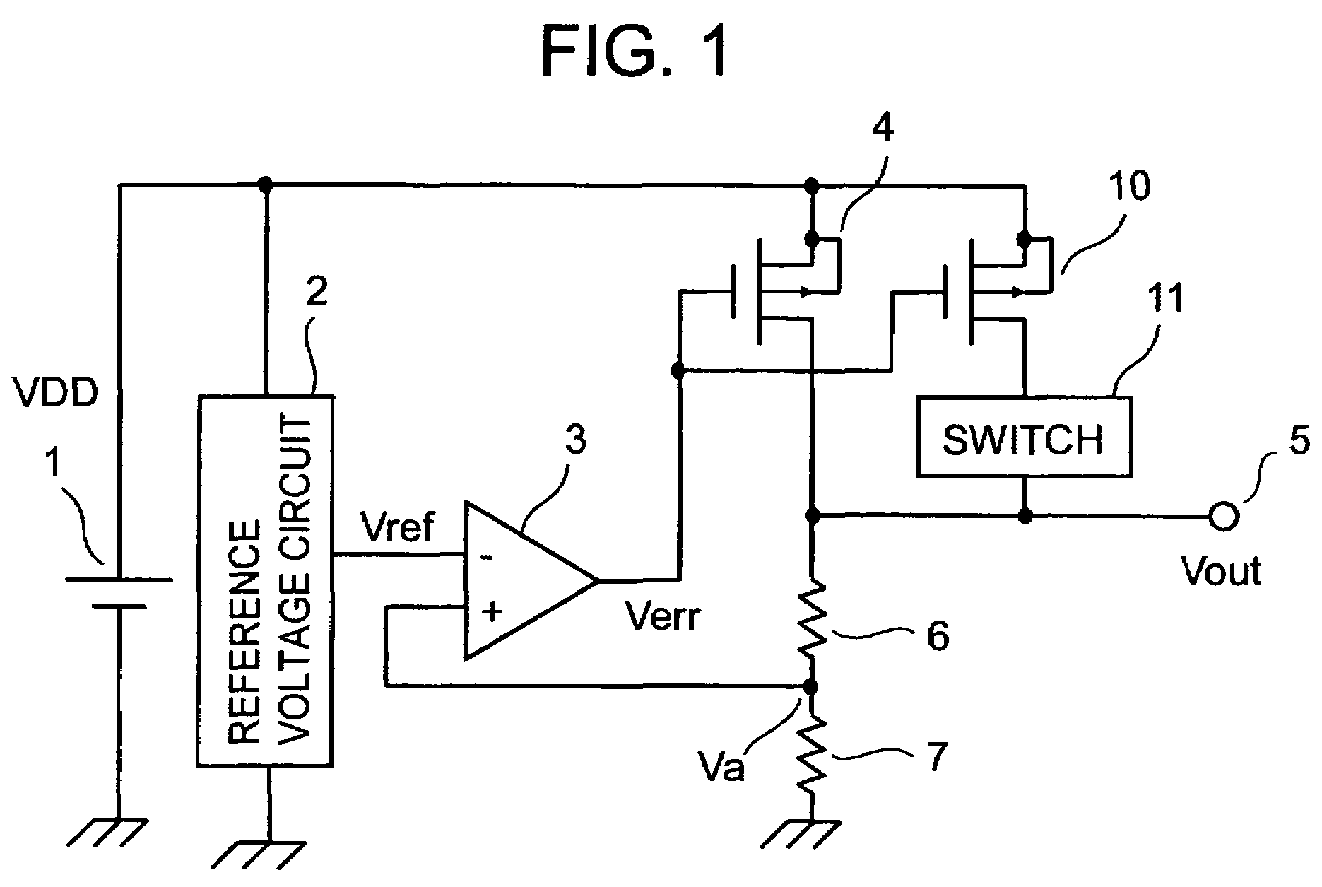
[0016]FIG. 1 is a circuit diagram of a voltage regulator according to a first embodiment of the present invention. The voltage regulator according to the first embodiment of the present invention includes a voltage regulator control circuit having a reference voltage circuit 2, bleeder resistors 6 and 7 for voltage-dividing an output voltage Vout of the voltage regulator, and an error amplifier 3 for amplifying a voltage difference between a reference voltage Vref from the reference voltage circuit 2 and a voltage Va appearing at a node between the bleeder resistors 6 and 7, output MOS transistors 4 and 10 connected in parallel, and a switch 11 for changing the effective W / L value (W is a channel width and L is a channel length) of the output transistors.

[0017]The switch 11 operates so as to be turned ON during a normal load operation and so as to be turned OFF during a light load operation.

[0018]When the switch 11 is turned ON, the output transistors 4 and 10 are both in output ope...

second embodiment

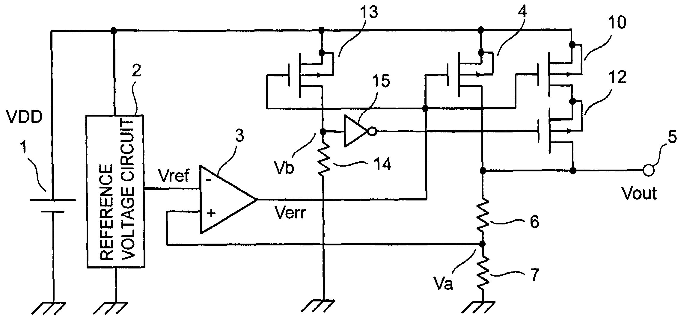
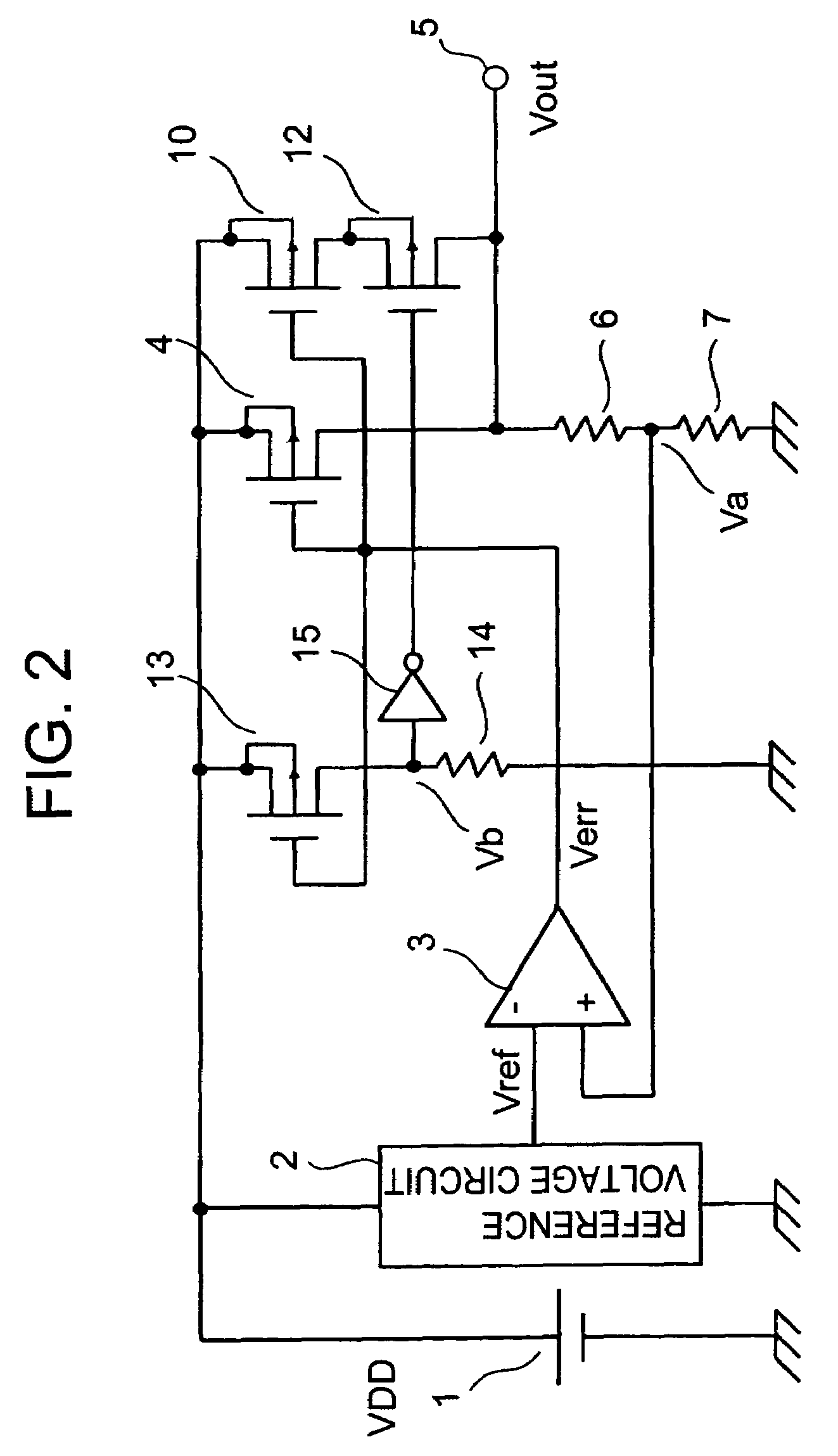
[0021]FIG. 2 is a circuit diagram of a voltage regulator according to a second embodiment of the present invention. The voltage regulator according to the second embodiment of the present invention includes a voltage regulator control circuit having a reference voltage circuit 2, bleeder resistors 6 and 7 for voltage-dividing an output voltage Vout of the voltage regulator, and an error amplifier 3 for amplifying a voltage difference between a reference voltage Vref from the reference voltage circuit 2 and a voltage Va appearing at a node between the bleeder resistors 6 and 7, output MOS transistors 4 and 10 connected in parallel, and a switching MOS transistor 12 for changing the effective W / L value of the output transistors.

[0022]A W / L value of the output transistors is changed by the switching transistor 12. The switching transistor 12 is controlled by an output current detection circuit including a transistor 13 connected in parallel with the output transistors 4 and 10, an outp...


PUM


Abstract

The present invention provides a voltage regulator capable of causing a large output current to flow during a heavy load operation, and of making a leakage current from output transistors small during a light load operation. The voltage regulator includes a plurality of output transistors and a circuit for changing connection of the output transistors to allow a W / L value of the output transistor to be changed. Moreover, the voltage regulator further includes an output current detection circuit for detecting an output current, and a circuit for changing connection of the output transistors based on the output current to allow a W / L value of the output transistors to be changed based on the output current.

Description

BACKGROUND OF THE INVENTION[0001]1. Field of the Invention[0002]The present invention relates in general to a voltage regulator, and more particularly to a voltage regulator capable of decreasing a leakage current from output transistors when a load is light.[0003]2. Description of the Related Art[0004]As shown in FIG. 3, a conventional voltage regulator includes a voltage regulator control circuit having a reference voltage circuit 2, bleeder resistors 6 and 7 for voltage-dividing an output voltage Vout appearing at an output terminal 5 of the voltage regulator, and an error amplifier 3 for amplifying a voltage difference between a reference voltage Vref from the reference voltage circuit 2 and a voltage Va appearing at a node between the bleeder resistors 6 and 7, and an output transistor 4. The voltage regulator operates at a power supply voltage VDD supplied from a voltage source 1.[0005]When an output voltage of the error amplifier 3 is assigned Verr, if the voltage Va is large...

Claims


Application Information

Patent Timeline
Patent Type & Authority Patents(United States)
IPC IPC(8): G05F1/10G05F1/575G05F1/56
CPCG05F1/575
Inventor SANO, KAZUAKI
Owner ABLIC INC
Why Eureka
Try Eureka