Bi-metallic structural component for vehicle frame assembly

a technology of bi-metallic structural components and vehicle frame assemblies, which is applied in the directions of roofs, transportation and packaging, vehicle arrangements, etc., can solve the problems of relatively difficult to perform such an operation in other directions, and the conventional welding technique is not well suited for securing together components

Active Publication Date: 2006-12-05
METALSA SA DE CV
View PDF43 Cites 32 Cited by
  • Summary
  • Abstract
  • Description
  • Claims
  • Application Information

AI Technical Summary

Benefits of technology

[0006]This invention relates to an improved structure for a structural component for use in a vehicle body and frame assembly. The vehicle body and frame assembly can be a ladder frame assembly including a pair of longitudinally extending side rails having a plurality of transverse cross members extending therebetween. The cross member is a multiple piece structure, including a central portion having a pair of end portions secured thereto. The central portion of the cross member is preferably formed from a first metallic material, while the end portions are preferably both formed from a second metallic material. The end portions of the cross member are preferably formed from the same metallic material as the respective side rails to which they are secured. The end portions of the cross member can be secured to the ends of the central portion by any desired process, such as by magnetic pulse welding. Similarly, the end portions of the cross member can be secured to the side rails by any desired process, such as by magnetic pulse welding or by conventional welding. The end portions of the cross member can extend either partially or completely through the respective side rails. If desired, a reinforcing and positioning collar can be secured to the end portions of the cross member adjacent to each of the side rails.

Problems solved by technology

Unfortunately, conventional welding techniques are not well suited for securing together components that are formed from dissimilar metallic materials.
Although magnetic pulse welding is an effective method for securing such structural components together in a manufacturing facility, it would be relatively difficult to perform such an operation elsewhere, such as in a small repair shop if a portion of the vehicle frame assembly was damaged and required replacement.

Method used


Image

  • Bi-metallic structural component for vehicle frame assembly
  • Bi-metallic structural component for vehicle frame assembly
  • Bi-metallic structural component for vehicle frame assembly

Examples


first embodiment

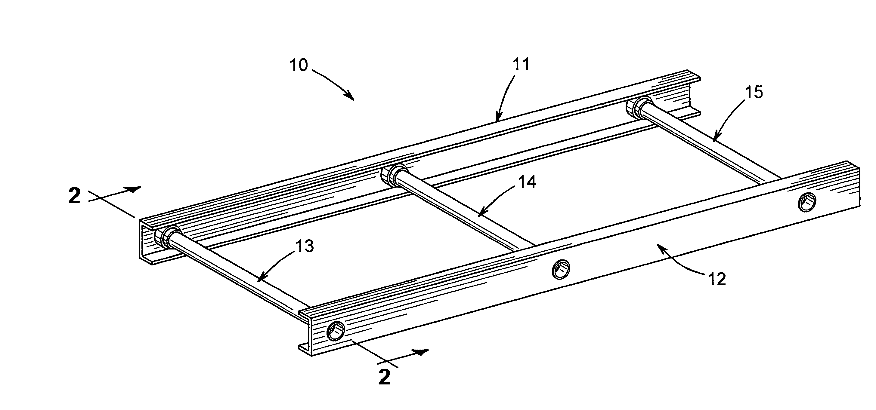
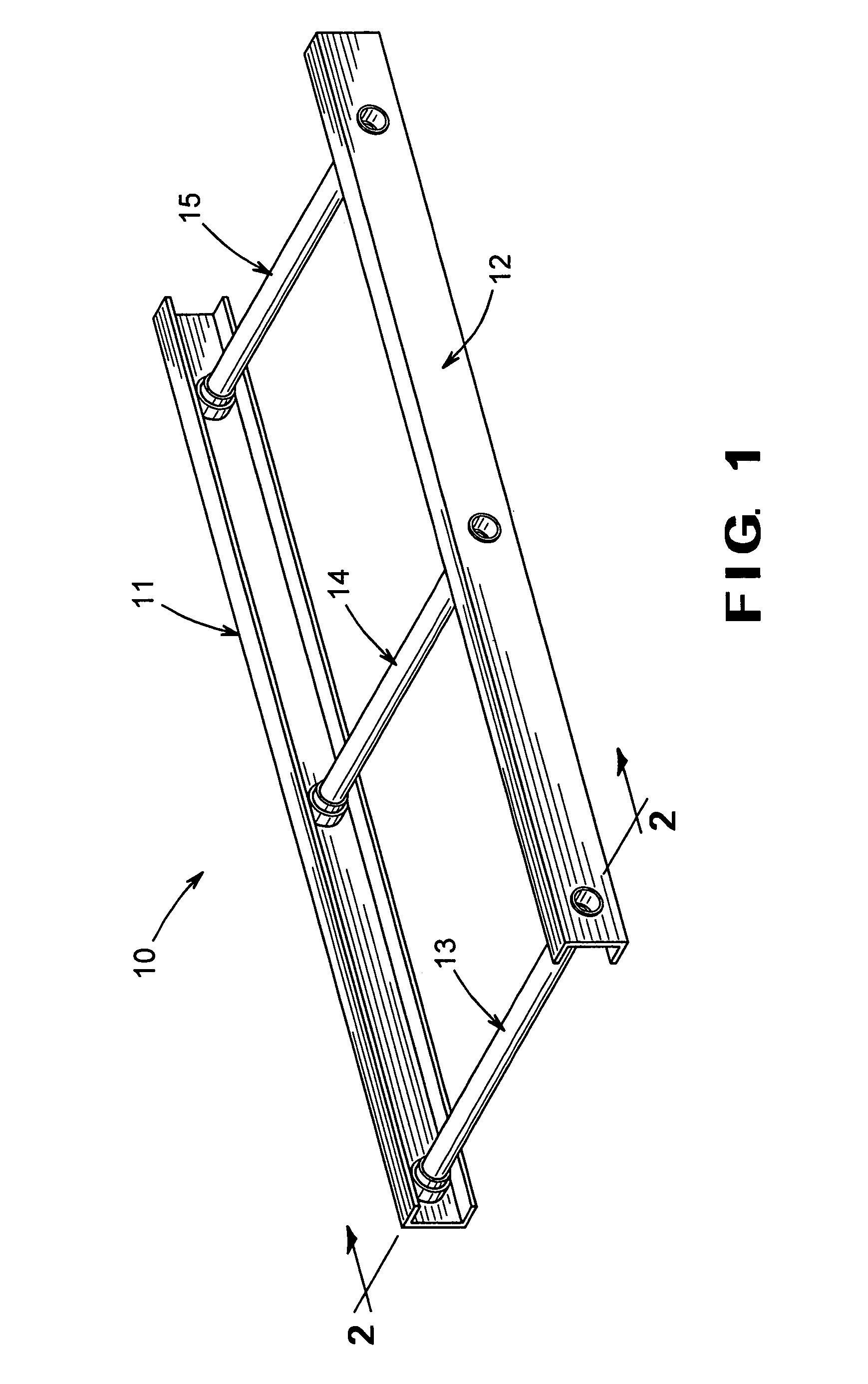
[0013]Referring now to the drawings, there is illustrated in FIG. 1 a vehicular body and frame assembly, indicated generally at 10, in accordance with this invention. The illustrated vehicular body and frame assembly 10 is a ladder frame type of vehicle frame assembly. However, it will be appreciated that the apparatus and method of this embodiment of the invention may be utilized in the manufacture of any type of vehicle body and frame assembly, such as a unitized type of body and frame assembly where the structural components of the body portion and the frame portion are combined into an integral unit, as discussed above. Additionally, as used herein, the term “vehicle frame assembly” is intended to include any type of vehicle structure, such as an upper body structure for use in or with a vehicle body and frame assembly.

[0014]The illustrated vehicular body and frame assembly 10 includes a pair of longitudinally extending side rails, indicated generally at 111 and 12, having a plu...

second embodiment

[0020]Referring now to FIG. 3, there is schematically illustrated a vehicle body and frame assembly, indicated generally at 30, that has been manufactured in accordance with the apparatus and method of this invention. The illustrated vehicle body and frame assembly 30 is also a ladder frame assembly. However, it will be appreciated that the apparatus and method of this embodiment of the invention may also be utilized in the manufacture of any type of vehicle body and frame assembly, such as a unitized body and frame assembly where the structural components of the body portion and the frame portion are combined into an integral unit, as discussed above.

[0021]The illustrated ladder frame assembly 30 includes a pair of longitudinally extending side rails, indicated generally at 31 and 32, having a plurality of transverse cross members, indicated generally at 33, 34, and 35, extending therebetween. The side rails 31 and 32 extend longitudinally along the length of the assembly 30 and ar...


PUM


Abstract

A vehicle body and frame assembly includes a pair of longitudinally extending side rails having a plurality of transverse cross members extending therebetween. The cross member is a multiple piece structure, including a central portion having a pair of end portions secured thereto. The central portion of the cross member is preferably formed from a first metallic material, while the end portions are preferably both formed from a second metallic material. The end portions of the cross member are preferably formed from the same metallic material as the respective side rails to which they are secured. The end portions of the cross member can be secured to the ends of the central portion by any desired process, such as by magnetic pulse welding. Similarly, the cross member can be secured to the side rails by any desired process, such as by magnetic pulse welding or by conventional welding. The end portions of the cross member can extend either partially or completely through the respective side rails. If desired, a reinforcing and positioning collar can be secured to the end portions of the cross member adjacent to each of the side rails.

Description

CROSS REFERENCE TO RELATED APPLICATION[0001]This application claims the benefit of U.S. Provisional Application No. 60 / 365,863, filed Mar. 19, 2002, the disclosure of which is incorporated herein by reference.BACKGROUND OF THE INVENTION[0002]This invention relates in general to body and frame assemblies for vehicles. In particular, this invention relates to an improved structure for a structural component for use in such a vehicle body and frame assembly.[0003]Many land vehicles in common use, such as automobiles, vans, and trucks, include a body and frame assembly that is supported upon a plurality of ground-engaging wheels by a resilient suspension system. The structures of known body and frame assemblies can be divided into two general categories, namely, separate and unitized. In a typical separate body and frame assembly, the structural components of the body portion and the frame portion of the vehicle are separate and independent from one another. When assembled, the frame po...

Claims


Application Information

Patent Timeline
Patent Type & Authority Patents(United States)
IPC IPC(8): B62D21/02B62D21/03B62D23/00B62D27/02B62D29/00
CPCB62D21/02B62D21/03B62D23/00B62D27/023B62D29/00
Inventor KIEHL, MARK W.DURAND, ROBERT D.
Owner METALSA SA DE CV
Why Eureka
Try Eureka