Multi-mode frequency synthesizer with temperature compensation

a frequency synthesizer and temperature compensation technology, applied in the direction of heat measurement, instruments, optical radiation measurement, etc., can solve the problems of reference oscillator modules, difficult monolithic integration with transceiver modules that are otherwise typically based on highly integrated solutions, and the complication of silicon-based microresonators in frequency synthesizers, etc., to achieve better optimization and low phase noise

Inactive Publication Date: 2006-12-05
NOKIA SOLUTIONS & NETWORKS OY
View PDF4 Cites 53 Cited by
  • Summary
  • Abstract
  • Description
  • Claims
  • Application Information

AI Technical Summary

Benefits of technology

[0013]It is an object of the present invention to eliminate the disadvantages of the prior art and to provide an improved method for stabilizing the frequency of a frequency synthesizer, and an improved frequency synthesizer.
[0015]The present invention is based on the principle that the resonator temperature is measured in order to electronically compensate for the temperature dependency and the resulting temperature dependent frequency shift. By measuring the temperature T of the MEMS resonator as depicted in FIG. 1c and by using the known frequency vs. temperature function fr(T), the resonance frequency becomes a precisely defined quantity that can be used to improve the stability of the prior art frequency synthesizer according to FIG. 1b.
[0016]In a preferred embodiment the temperature measurement is based on exciting two modes in a MEMS resonator having different temperature coefficients. By looking at the frequency shift of the two modes, the change in temperature can be measured and electrically compensated. This method has the following advantages: 1) no temperature sensor is needed eliminating temperature transient hysteresis associated with temperature difference of the sensor and the resonator, 2) frequency measurement is accurate and is straightforward to realize digitally, and 3) no additional sensors are needed as the resonator is also the sensor. This simplifies fabrication and reduces costs.
[0018]The main advantage of the methods presented in the present invention is that because the rather large (but predictable) temperature dependence of a MEMS-oscillator is taken into account directly in the frequency synthesis, the long-term stability and low phase noise for the reference oscillator can be better optimized as the oscillator itself can be left running uncompensated. Using the described methods, the MEMS-reference oscillator can be (monolithically) integrated as a part of a wireless transceiver module.

Problems solved by technology

The central disadvantages of quartz crystal reference oscillator modules are their rather bulky size and difficulty for monolithic integration with the transceiver module that is otherwise typically based on highly integrated solutions.
However, a fundamental complication in using silicon-based microresonators in frequency synthesizers arises from their large temperature coefficient, typically the df / dT from −10 to −30 ppm / K.
Such a temperature dependence is far too large for a reference application if left unaccounted for.

Method used


Image

  • Multi-mode frequency synthesizer with temperature compensation
  • Multi-mode frequency synthesizer with temperature compensation
  • Multi-mode frequency synthesizer with temperature compensation

Examples


Embodiment Construction

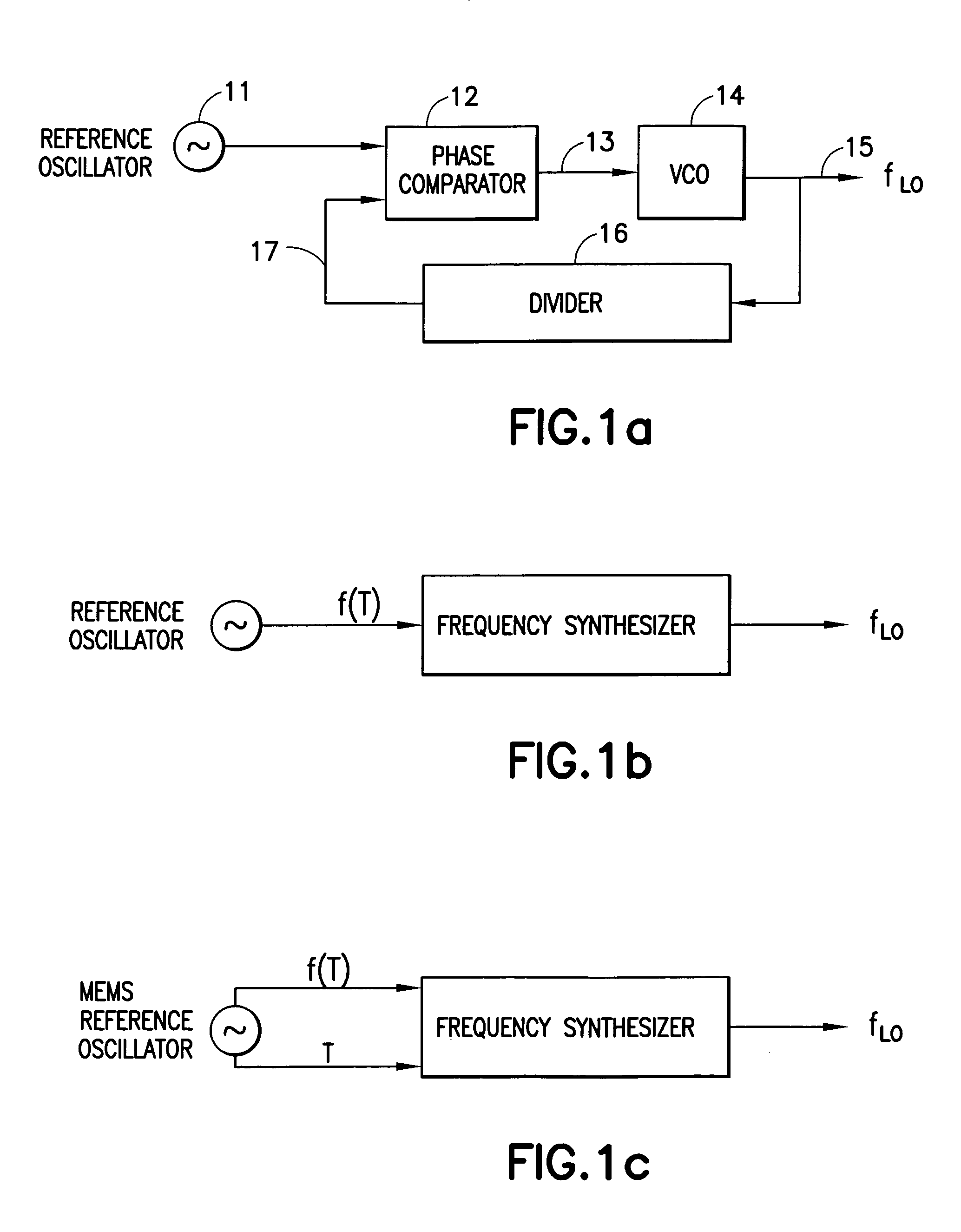
[0030]The present invention relates to a method for stabilizing the frequency of a frequency synthesizer by using a reference oscillator coupled to a voltage controlled oscillator (VCO) using a phase locked loop (PLL) or a frequency comparison control, wherein a reference MEMS oscillator is utilized for stabilization of the VCO, whereby by measuring the temperature T of the MEMS resonator and by using its known frequency vs. temperature function fr(T), the output frequency becomes a precisely defined quantity that can be used as a reference in frequency synthesizers.

[0031]In the following three stabilization methods are presented for MEMS-oscillator-based frequency synthesizers.

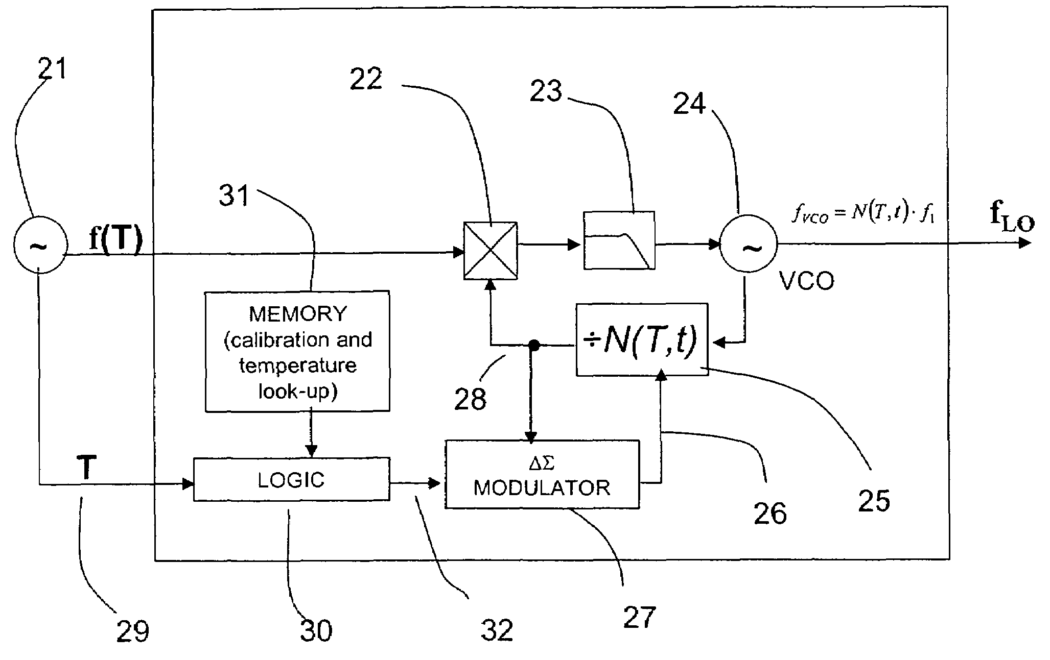
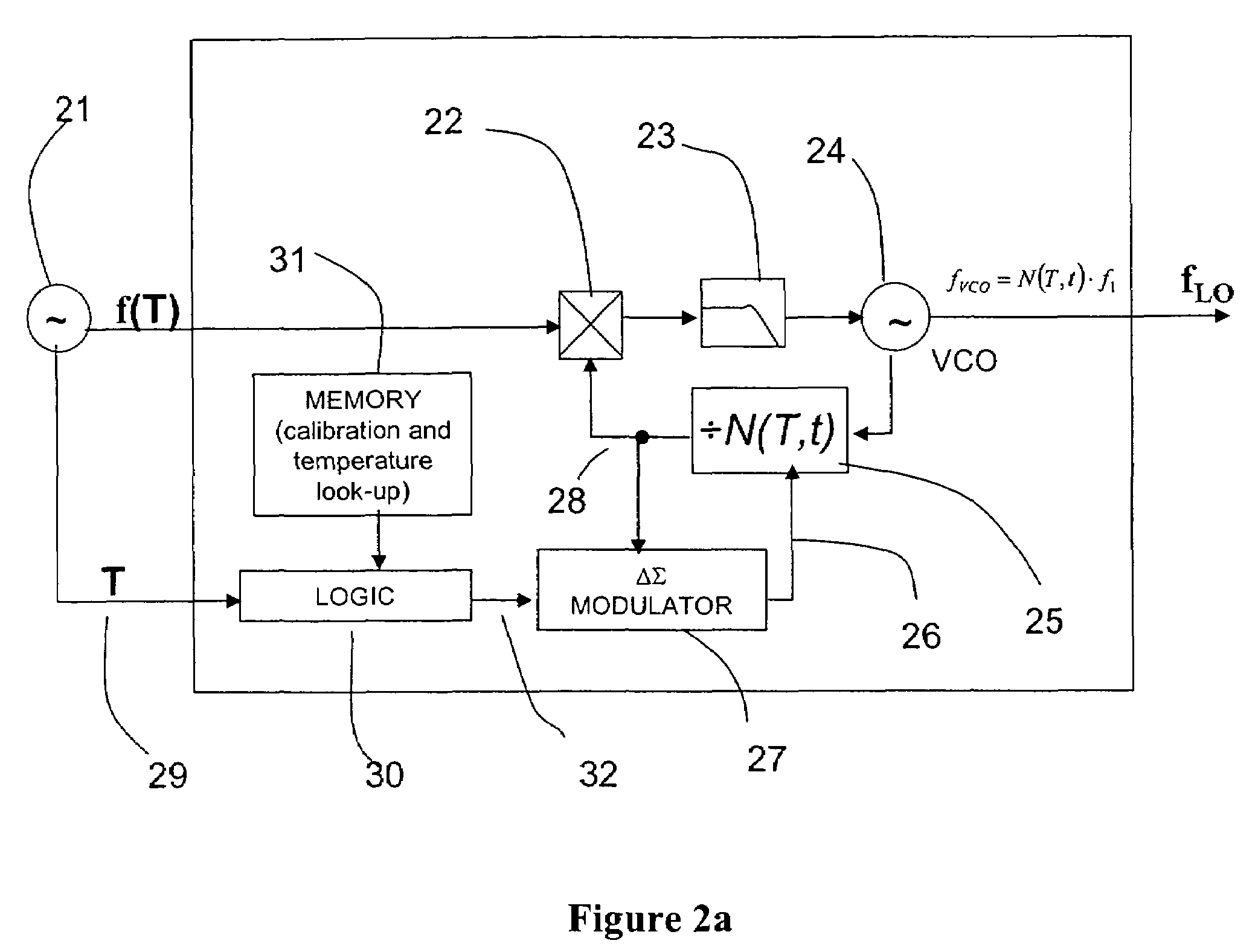
[0032]According to a first method, with a block diagram depicted in FIG. 2a, the VCO 24 generates the LO-frequency (e.g. at 1 GHz) fLo. The MEMS-reference oscillator 21 is typically operated at a significantly lower frequency (e.g. at 10 MHz). The VCO output frequency is divided in the divider 25 in order to ...


PUM


Abstract

Method for stabilizing the frequency of a frequency synthesizer by means of a reference oscillator unit coupled to a voltage controlled oscillator (VCO) and a frequency synthesizer, wherein the synthesizer is provided with a phase locked loop (PLL) to stabilize the operation of the voltage controlled oscillator, wherein the reference oscillator unit is a MEMS (MicroElectromechanicalSystems) reference oscillator unit, the temperature of the MEMS reference oscillator unit is measured, and the output frequency is corrected according to the measured temperature by using a frequency / temperature function.

Description

CROSS REFERENCE TO RELATED APPLICATION[0001]This application is a continuation of International Patent Application No. PCT / FI2004 / 000384, filed on Jun. 24, 2004.FIELD OF INVENTION[0002]The present invention relates to a method for stabilizing the frequency of a frequency synthesizer. More specifically, the present invention relates to a method for stabilizing the frequency of a frequency synthesizer by means of a reference oscillator coupled to a voltage controlled oscillator (VCO) by using a phase locked loop (PLL). The present invention also relates to a frequency synthesizer.BACKGROUND OF THE INVENTION[0003]In typical modern wireless transceivers the communication frequency is derived from a reference oscillator. For example, in a wireless hand-set a frequency based on the reference oscillator is used to initiate the communication with a base station. After the connection has been established, the frequency accuracy may further be improved by various synchronization methods, but ...

Claims


Application Information

Patent Timeline
Patent Type & Authority Patents(United States)
IPC IPC(8): H03B1/00H03B5/30H03L1/02H03L7/06H03L1/00H03L7/085H03L7/197
CPCH03L1/026H03L1/027H03L7/085H03L7/197H03L7/1976G01K7/32
Inventor MATTILA, TOMIJAAKKOLA, OLLIKAAJAKARI, VILLEOJA, AARNESEPPA, HEIKKI
Owner NOKIA SOLUTIONS & NETWORKS OY
Why Eureka
Try Eureka