Display apparatus

a technology of display apparatus and display screen, which is applied in the field of display screen, can solve the problems of long cable use, phase difference generation between r, g, b signals, and failures to occur such as parts of the end of displayed characters becoming colored, and achieve the effects of simplifying circuit structure, short period of time, and reducing phase correction amoun

Active Publication Date: 2006-12-05
NEC DISPLAY SOLUTIONS LTD
View PDF21 Cites 11 Cited by
  • Summary
  • Abstract
  • Description
  • Claims
  • Application Information

AI Technical Summary

Benefits of technology

[0010]According to the above structure, the phase detection means detects respective phases of a plurality of color signals such as R, G, B signals relative to a reference signal such as a horizontal synchronization signal, and, based on the result of this detection, the calculation means determines the color signal from among the plurality of color signals that is delayed the most relative to the reference signal, and also determines phase differences of the remaining color signals relative to the most delayed color signal. The control means controls a delay amount of the delay means of the color signal that is delayed the most such that this delay amount is a predetermined amount, and also controls the delay amounts of the delay means of the other color signals in accordance with the phase differences of the other color signals. As a result, it is possible to downsize the phase correction amount and simplify the circuit structure, and to perform phase adjustment automatically in a short period of time.
[0011]Accordingly, because a structure is employed in which the color signal having the largest delay is determined from the plurality of color signals, and the phase differences between this signal and the remaining color signals are determined, and the delay amounts of each color signal are controlled in accordance with these phase differences, it is possible to reduce the phase amount to be corrected and perform adjustment that removes the phase differences between each color signal. As a result, the size of the circuitry can be reduced and phase adjustment can be performed automatically in a short period of time. Moreover, it becomes possible to perform phase adjustment automatically in accordance with the type of input signal even when the present invention is used in a multi-sync display apparatus.
[0012]Furthermore, by employing a structure in which each delay circuit is formed by an analog signal delay circuit and a digital signal delay circuit, and performing analog control and digital control in combination, phase adjustment can be performed even more accurately.

Problems solved by technology

In a conventional display system in which color signals such as R (red), G (green), and B (blue) signals generated by a personal computer (PC) are transmitted to a display apparatus via a cable, there are many cases in which the display apparatus is located at a considerable distance from the PC, resulting in a long cable needing to be used.
If the signal transmission distance is lengthened like this, the problem arises of phase differences being generated between the R, G, B signals.
In particular, in the case of a high resolution display apparatus that uses a liquid crystal display element, even if there is only a slight discrepancy between the phases of the R, G, and B signals, failures sometimes occur such as portions of the ends of displayed characters becoming colored.
In some modern systems there are even cases when the PC and the display apparatus may be located as much as 300 meters away from each other, so that the above problem of the phase difference generation becomes an extremely serious one.
Therefore, not only does the adjustment take time, but the further problem of an increased circuitry size arises.
In addition, in the case of a multi-sync display apparatus in which a plurality of types of R, G, B signals each having different synchronization signals are selectively input, because the phase difference that needs to be corrected is different for each type of input signal, the problem arises that manual adjustment must be performed again every time the type of input signal changes.

Method used


Image

  • Display apparatus
  • Display apparatus
  • Display apparatus

Examples


first embodiment

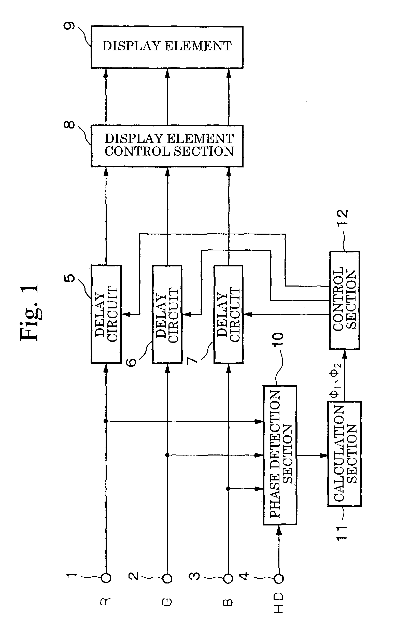
[0019]FIG. 1 is a block diagram showing the structure of the display apparatus according to the present invention.

[0020]In FIG. 1, the symbol 1 indicates an input terminal that receives the input of R signals from a PC (not shown) serving as a signal source, the symbol 2 indicates an input terminal that receives the input of G signals also from a PC, and the symbol 3 indicates an input terminal that receives the input of B signals also from a PC. The symbol 4 indicates an input terminal that receives the input of horizontal synchronization signals HD also from a PC. The symbol 5 indicates a delay circuit having a variable delay amount that delays input R signals, the symbol 6 indicates a delay circuit having a variable delay amount that delays input G signals, and the symbol 7 indicates a delay circuit having a variable delay amount that delays input B signals. The symbol 8 indicates a display element control section that converts the delayed R, G, B signals into display signals of ...

second embodiment

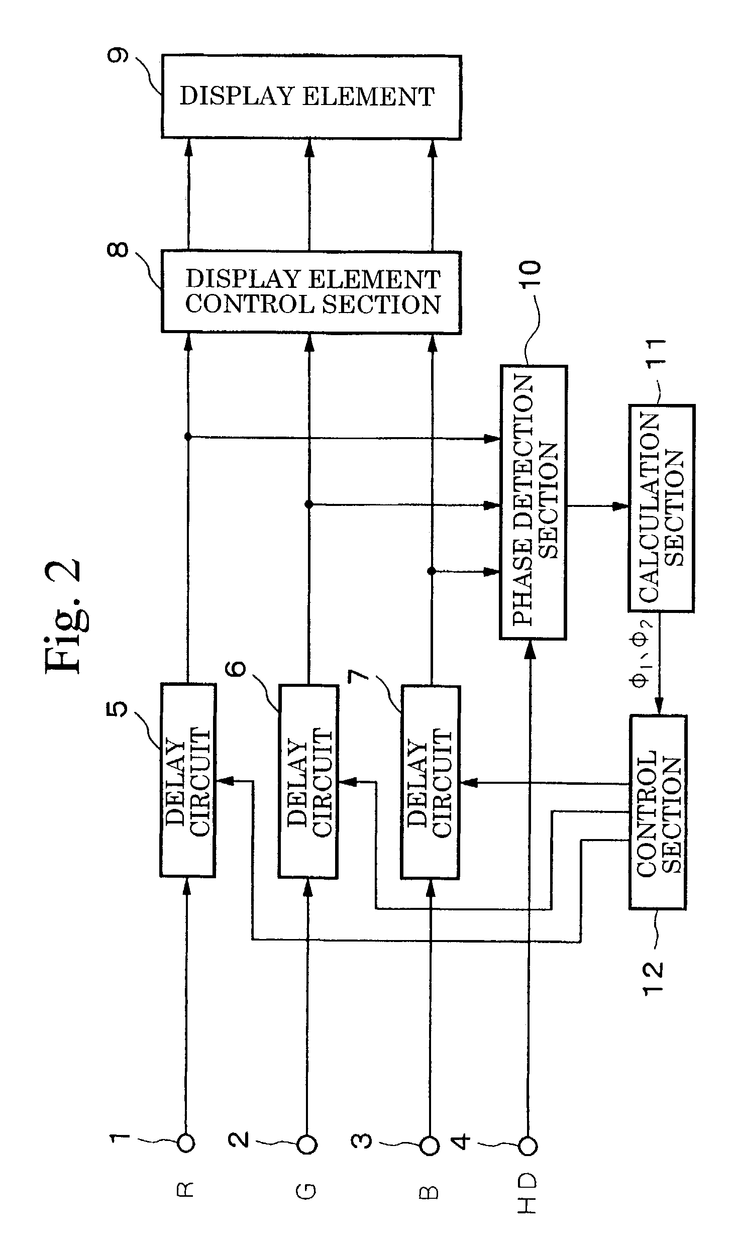
[0027]FIG. 2 is a block diagram showing the structure of the display apparatus according to the present invention, and the same descriptive symbols are given to portions that correspond to portions in FIG. 1 and a description thereof is not repeated.

[0028]The above described first embodiment shown in FIG. 1 employs a feed forward control mode in which a phase detection section 10 is provided upstream from the delay circuits 5, 6, and 7, and the delay amount of each delay circuit is controlled by detecting the phases of the R, G, B signals input from the PC serving as a signal source. However, the present embodiment employs a feed back control mode in which, as is shown in FIG. 2, the delay amounts of the respective delay circuits 5, 6, and 7 are controlled with the phase detection section 10 provided downstream from the delay circuits 5, 6, and 7.

[0029]Next, the operation of the above structure will be described.

[0030]In an initial state, the delay amounts of the respective delay ci...

third embodiment

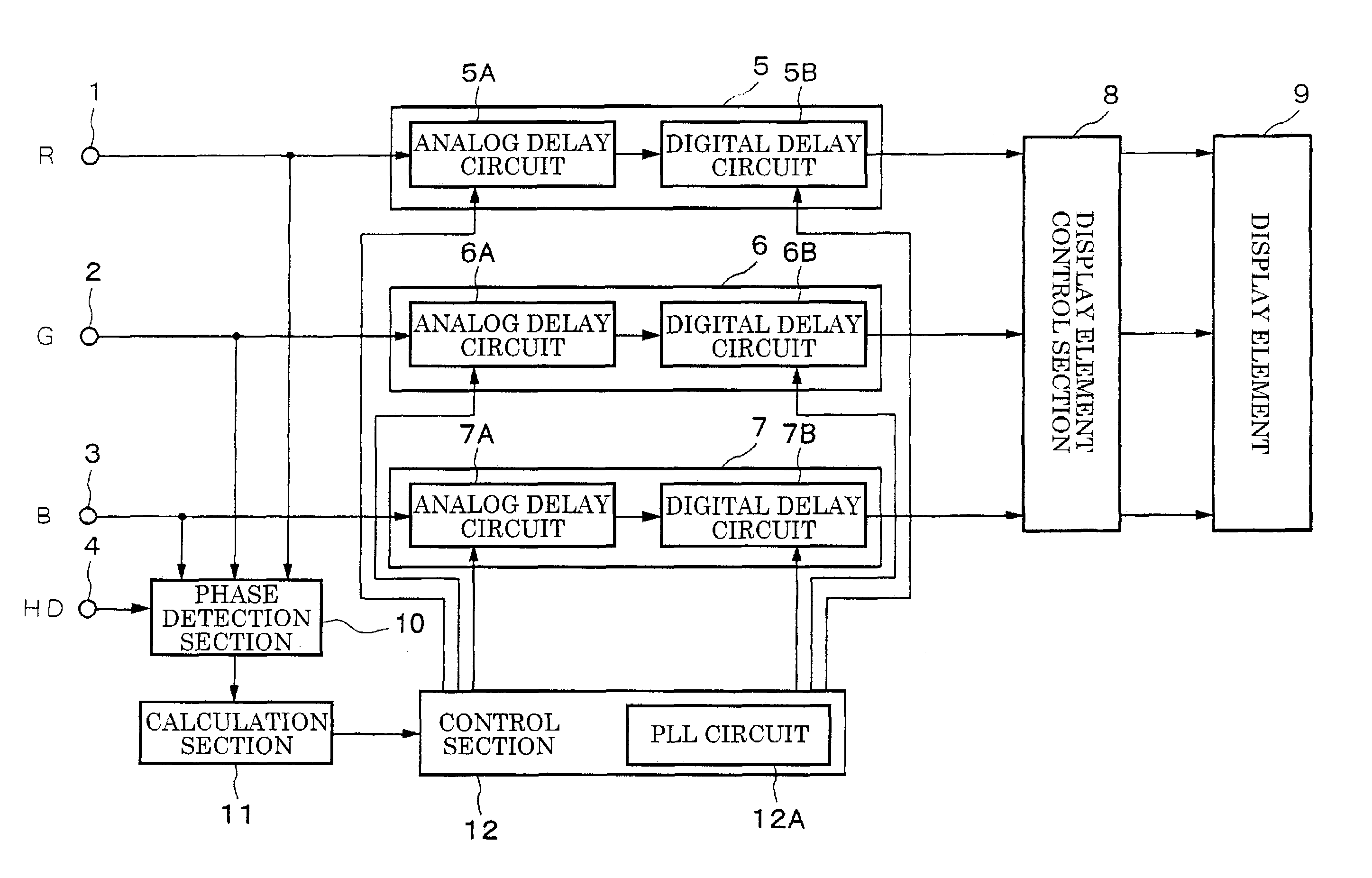
[0032]FIG. 3 is a block diagram showing the structure of the display apparatus according to the present invention, and the same descriptive symbols are given to portions that correspond to portions in FIG. 1 and a description thereof is not repeated.

[0033]In the present embodiment, as is shown in FIG. 3, the delay circuit 5 is formed by an analog delay circuit 5A and a digital delay circuit 5B, the delay circuit 6 is formed by an analog delay circuit 6A and a digital delay circuit 6B, and the delay circuit 7 is formed by an analog delay circuit 7A and a digital delay circuit 7B.

[0034]The delay amounts of the analog delay circuits 5A, 6A, and 7A are analog controlled by the control section 12 as delay amounts of less than 1 dot (i.e., pixel). The delay amounts of the analog delay circuits 5B, 6B, and 7B are digitally controlled in 1 dot units based on dot clocks by the control section 12 as delay amounts of 1 dot or more. A PLL circuit 12A that generates dot clocks by operating on th...


PUM


Abstract

In a display apparatus that receives and then displays R, G, B signals transmitted from a computer via a cable, when correcting phase differences between the respective signals that are generated while the signals are being transmitted, the phase correction amount can be reduced and phase adjustment performed automatically by a simple circuit structure. In a phase detection section, the phases of R, G, B signals input from a PC relative to a horizontal synchronization signal HD are detected, and based on the result of these detections, a calculation section 11 determines which color signal from the R, G, B signals has the greatest delay relative to the horizontal synchronization signal HD, and also determines the phase differences of the remaining two signals relative to the most delayed signal. A control section then performs control such that the delay amount of the delay circuit of the most delayed color signal out of the delay circuits is set to zero, and the delay amounts of the delay circuits of the remaining two color signals are controlled in accordance with the above phase differences.

Description

BACKGROUND OF THE INVENTION[0001]1. Field of the Invention[0002]The present invention relates to a display apparatus that is favorably used in a display system that displays on a liquid crystal element or the like color signals such as R, G, B signals output from a PC.[0003]2. Description of the Related Art[0004]In a conventional display system in which color signals such as R (red), G (green), and B (blue) signals generated by a personal computer (PC) are transmitted to a display apparatus via a cable, there are many cases in which the display apparatus is located at a considerable distance from the PC, resulting in a long cable needing to be used. If the signal transmission distance is lengthened like this, the problem arises of phase differences being generated between the R, G, B signals.[0005]In particular, in the case of a high resolution display apparatus that uses a liquid crystal display element, even if there is only a slight discrepancy between the phases of the R, G, and...

Claims


Application Information

Patent Timeline
Patent Type & Authority Patents(United States)
IPC IPC(8): G09G5/10G09G5/00G09G3/36G09G1/28G09G3/20H04N9/64
CPCG09G1/285
Inventor ARAI, YUTAKAABE, MASATOSHI
Owner NEC DISPLAY SOLUTIONS LTD
Why Eureka
Try Eureka