Method of generating an inspection program and method of generating a visual display

a visual display and inspection program technology, applied in the direction of electrical programme control, program control, instruments, etc., can solve the problems of inability of the probe to follow uninterrupted inspection paths on a blisk, the complexity of the component under inspection, and the economic unviability of conventional inspection, so as to reduce the amount of time

Inactive Publication Date: 2006-12-05
ROLLS ROYCE PLC
View PDF17 Cites 50 Cited by
  • Summary
  • Abstract
  • Description
  • Claims
  • Application Information

AI Technical Summary

Benefits of technology

[0010]An object of the present invention, therefore, is to reduce the amount of time needed to specify a probe inspection path.
[0020]It is thus possible to associate with each selected shape characteristic a standard measuring probe inspection path (which may comprise a plurality of sub-paths, each having e.g. an initial probe stand off position, measurement start and finish positions, and a final probe stand off position). The nominal geometry data and the inspection requirement data determines the approximate dimensions of that path. However, by carefully defining the standard inspection path, the computer can ensure that the probe can access all points along the path without colliding with adjacent parts of the component.
[0022]Preferably, the inspection path is determined so as to minimise the number of (generally time-consuming) probe changes. For example, if a number of spaced plane sections are to be measured on a particular blade of a blisk, and the probe can only measure the flanks of each section by using a relatively long probe, but for measurement accuracy it is desirable to use a relatively short probe to measure the critical leading edge and trailing edge portions of the sections, the inspection path can be determined so that the flanks of all the sections are measured before any of the leading edge and trailing edge portions. Thus in this example only one probe change is required during the execution of the inspection path.
[0026]The inspection requirement data may further specify scan parameters such as the measurement point density along the inspection path for each selected shape characteristic and / or the probe type to be used for each selected shape characteristic. In this way the operator can influence the number and accuracy of the actual component coordinates which are measured when the computer-controlled coordinate measuring probe is moved along the inspection path under file control of the inspection program controls. Additionally or alternatively, default settings can be used for some or all or the scan parameters.
[0051]It is known to generate visual displays by scaling the tolerance limits and actual profile so that the spacing between the inner and outer tolerance limits is expanded relative to distances along which the actual profile extends, but the position of the actual profile relative to the spacing is preserved. Thus if a particular point on the actual profile touches or crosses the inner or outer tolerance limit, that point will still appear to touch or cross the tolerance limit on the superimposed and scaled visual display. An operator can thus readily determine from the visual display whether the actual profile is within the tolerance limits.
[0058]Thus the method advantageously provides a visual display in which tolerance limit cross over can be avoided so that the superimposed and scaled tolerance limits and actual profile better preserve the original shape of the component. For example, in the case of the visual display of an aerofoil plane section, the inner tolerance limit for the section can prevented from being inwardly displaced on scaling, thereby avoiding cross over of those portions of the inner tolerance limit corresponding to the flanks of the aerofoil plane section.

Problems solved by technology

A problem can arise, however, when the component under inspection has a more complex shape.
It is often not possible for the probe to follow uninterrupted inspection paths on a blisk because the tight angular packing of the blades forces the operator to access different surface positions from different sides of the blisk.
Indeed the amount of time can result in conventional inspection becoming economically unviable.

Method used


Image

  • Method of generating an inspection program and method of generating a visual display
  • Method of generating an inspection program and method of generating a visual display
  • Method of generating an inspection program and method of generating a visual display

Examples


Embodiment Construction

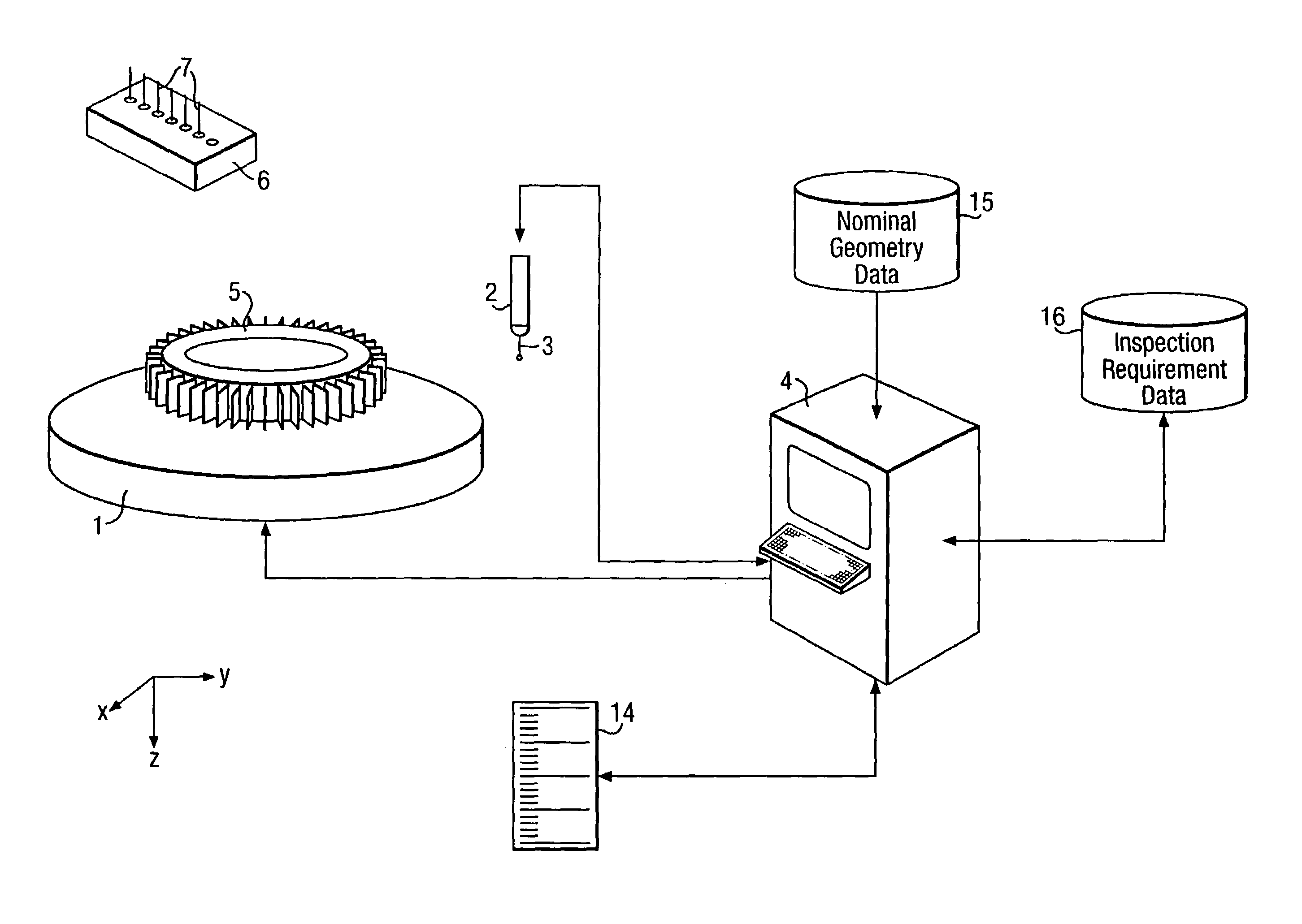
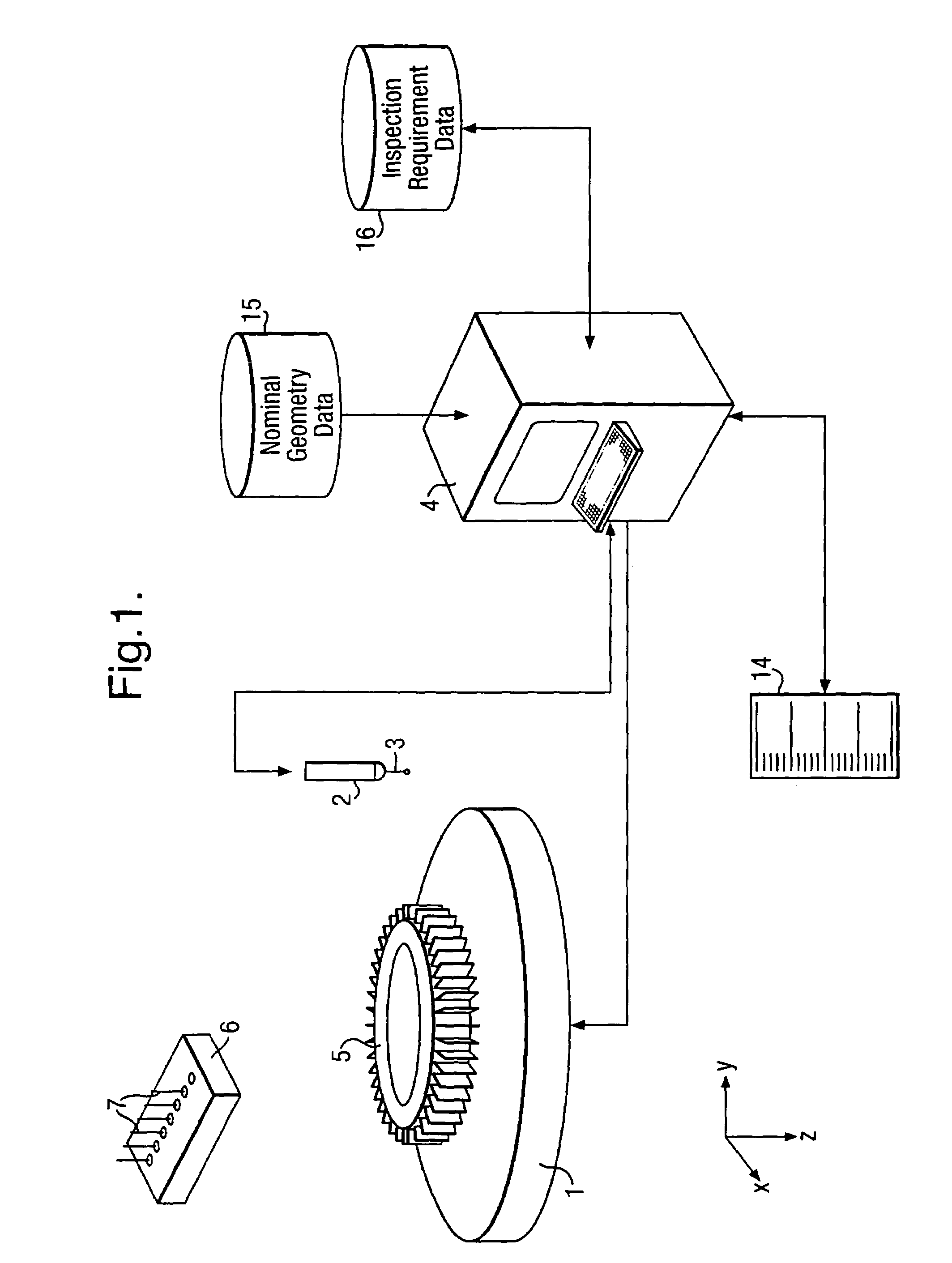
[0092]FIG. 1 shows a block diagram of a programmable CMM system for inspecting a component with a coordinate measuring probe.

[0093]The CMM comprises a turntable 1, a quill 2 (providing z-direction movement) with a coordinate measuring probe 3 at the distal end, a carriage assembly (not shown) which moves the quill in the x- and y-directions, and a central programmable computer 4 (which takes the form of a command console) for controlling the turntable, Quill and measuring probe, and for receiving measurement signals from the probe. The component to be inspected, in this exemplary embodiment a blisk 5, is mounted on the turntable.

[0094]A probe change station 6 spaced from the turntable carries a plurality of alternative measuring probes 7 which can be interchangeably mounted at the end or the quill.

[0095]The measuring probe has a finger (formed e.g. of carbon fibre) which terminates at one end in a small hard industrial ruby sphere and at the other end joins to a connecting member wh...


PUM


Abstract

A computer-implemented method of generating an inspection program for a computer-controlled coordinate measuring probe comprises the steps of:(a) receiving nominal geometry data for a component,(b) receiving inspection requirement data specifying one or more selected shape characteristics of the component,(c) determining from the nominal geometry data and the inspection requirement data an inspection path for a computer-controlled coordinate measuring probe, the inspection path enabling the measuring probe to measure actual component coordinates associated with the selected shape characteristics, and(d) generating an inspection program for moving the computer-controlled coordinate measuring probe along the inspection path.

Description

[0001]This is a continuation of PCT / GB2003 / 001893 filed May 14, 2003FIELD OF THE INVENTION[0002]The present invention relates to a method of generating an inspection program, a method of inspecting a component, a method of generating a visual display, and a method of determining whether a component conforms to tolerances.BACKGROUND OF THE INVENTION[0003]Manufactured components often have to conform to dimensional and / or geometrical tolerances. These mat be specified by the manufacturer or ultimate user of the component e.g. to ensure that the component behaves correctly in service. Thus it is common to subject components to post-manufacture inspection procedures.[0004]A known technique for determining the dimensional accuracy of components involves driving a computer-controlled coordinate measuring probe or stylus over the surface of he component. Such a probe typically comprises a stiff elongate member (formed e.g. of carbon fibre) having a small hard (typically industrial ruby) sp...

Claims


Application Information

Patent Timeline
Patent Type & Authority Patents(United States)
IPC IPC(8): G05B19/19G01B21/04G05B19/401G06F19/00
CPCG01B21/04G05B19/401G05B2219/35475G05B2219/36365G05B2219/37079G05B2219/37193G05B2219/37205G05B2219/37443G05B2219/37449
Inventor HOUGH, GERALD W.
Owner ROLLS ROYCE PLC
Why Eureka
Try Eureka