
Image detector for x-ray devices with rear-contact organic image sensors

a technology of organic image sensor and image detector, which is applied in the direction of x/gamma/cosmic radiation measurement, radiofrequency controlled devices, instruments, etc., can solve the problems of low detection sensitivity, low detection efficiency, and low detection efficiency, and achieve high detection sensitivity, high fill factor, and high utilization of detector surface

Inactive Publication Date: 2006-12-12
SIEMENS HEALTHCARE GMBH
View PDF12 Cites 12 Cited by
  • Summary
  • Abstract
  • Description
  • Claims
  • Application Information

AI Technical Summary

Benefits of technology

[0009]An object of an embodiment of the invention is to specify an image detector for x-ray images which has a flat arrangement of detector pixels with a high area fill factor, that is to say with high utilization of the detector surface by detector pixel points. At the same time, the image detector preferably exhibits a good detection sensitivity and good detection dynamics, and should be capable of being connected electrically without difficulty and produced in an uncomplicated manner.
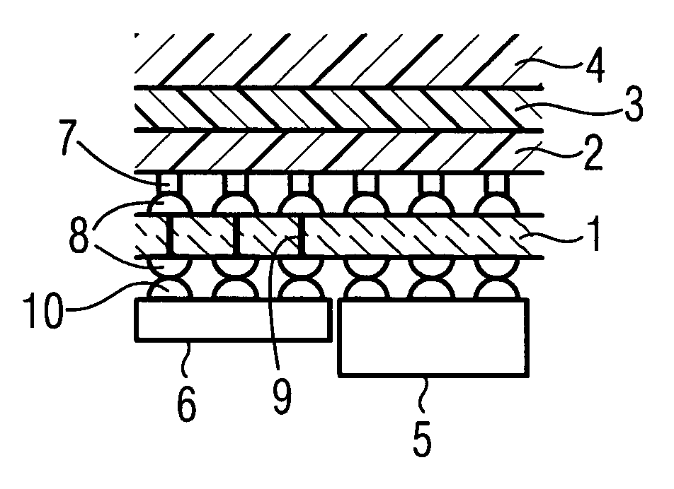
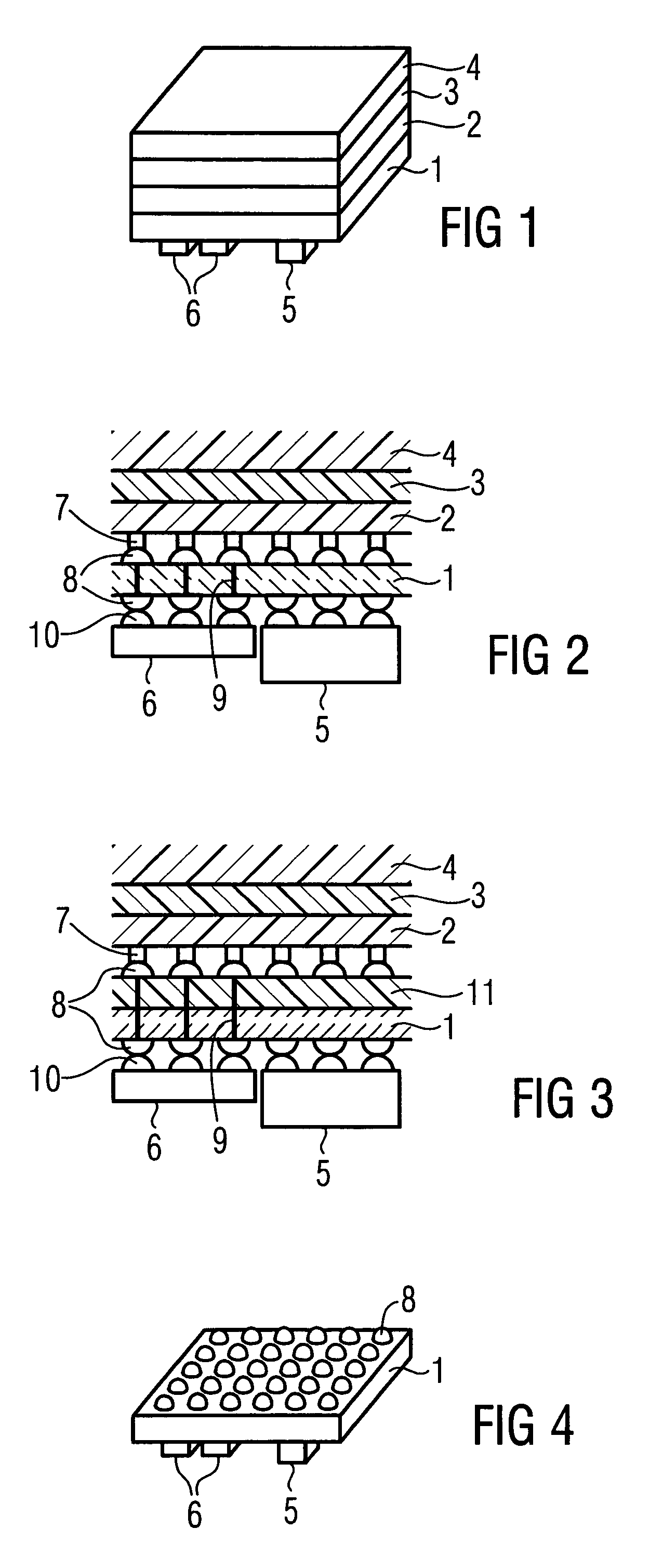
[0012]Making contact on the rear permits the production of electric connections by means of high integration technologies which can be applied without difficulty instead of the bonding techniques previously used. This is because contact surfaces and sensors are no longer arranged immediately beside one another. In addition, dead zones in the detector surface, which were caused by the bonding pads previously required, are avoided and therefore the fill factor is increased. This permits, in particular, the use of the image detector in computer tomography. In addition, the length of the analog signal propagation paths are reduced to a minimum by an embodiment of the invention.
[0013]In an advantageous refinement of an embodiment of the invention, the rear contacts of the detector pixel points are connected to plated-through holes in a substrate which lead to the rear of the substrate. By using such a substrate, additional functionalities can be implemented. For instance, the electric circuit can be configured more complexly and the level of integration can be increased. In addition, the substrate can impart the requisite mechanical stability and shape to the image detector.

Problems solved by technology

Organic photodiodes are, firstly, very uncomplicated and cost-effective and, secondly, they have the recording dynamics which are necessary for applications in computer tomography and, inter alia, exhibit no persistence.

Method used


Image

  • Image detector for x-ray devices with rear-contact organic image sensors
  • Image detector for x-ray devices with rear-contact organic image sensors

Examples


Embodiment Construction

[0021]An image detector according to an embodiment of the invention is illustrated in FIG. 1 in a perspective view, not to scale. For the construction of the image detector, the substrate 1 is the carrying element. Use is made of a large-area, mechanically stable substrate, for example one of Al2O3 ceramic. Depending on the size of the detector and the intended use, substrates of organic materials or film substrates can also be used.

[0022]Illustrated above the substrate 1 is a photosensitive layer 2, which forms the photosensors. The photosensitive layer 2 includes a material which produces an electrical signal as a function of the occurrence of electromagnetic radiation, preferably of an organic photodiode material. However, semiconductor detectors, semiconducting materials or photocells are also suitable. The photosensitive layer 2 can either be formed as a continuous, closed layer of the photosensitive material or assembled from individually structured pixel points of this materi...


PUM


Abstract

An image detector for an x-ray device includes photosensors which have at least two contacts on which an electrical signal occurs when x-rays are detected. In each case, at least one contact of the photosensors is arranged on its rear side, facing away from the image source. Further, the material used for the photosensors is an organic photodiode material.

Description

[0001]The present application hereby claims priority under 35 U.S.C. §119 on German patent application number DE 10244177.4 filed Sep. 23, 2002, the entire contents of which are hereby incorporated herein by reference.FIELD OF THE INVENTION[0002]The invention generally relates to an electronic image detector for an x-ray device.BACKGROUND OF THE INVENTION[0003]In x-ray diagnostics, use is increasingly made of electronic image detectors. While, in particular, individual recordings are still frequently recorded with x-ray sensitive film material, even nowadays, it is desirable to use electronic image detectors, above all in the case of series of x-ray recordings. They permit, firstly, the recording of faster image sequences on account of the lower requisite exposure times and dispensing with the mechanical film transport, and, secondly, the data registered can be supplied immediately for electronic evaluation. For example, in computer tomography, a series of thousands of individual re...

Claims


Application Information

Patent Timeline
Patent Type & Authority Patents(United States)
IPC IPC(8): G01T1/24G01T1/29H01L27/146
CPCG01T1/2928H01L27/14661H01L27/14663
Inventor HEISMANN, BJOERNLEPPERT, JUERGENVON DER HAAR, THOMAS
Owner SIEMENS HEALTHCARE GMBH
Learn More