Eureka AIR delivers breakthrough ideas for toughest innovation challenges, trusted by R&D personnel around the world.

Network for data transmission

Inactive Publication Date: 2006-12-12
JETTER AG
View PDF17 Cites 18 Cited by
  • Summary
  • Abstract
  • Description
  • Claims
  • Application Information

AI Technical Summary

Benefits of technology

[0008]It is therefore an object of the invention to create a network suitable for the control of industrial processes which makes possible a data exchange having good reproducibility in regard to the time required.
[0012]The invention is based on the general idea of preventing colliding data transmissions in a data line through a particular physical structure of the process control and / or through control of the data exchange. Incalculable delay times when accessing a bus and / or a data line are thereby prevented from occurring and the time needed for a data exchange can be calculated exactly and / or within very narrow boundaries.
[0014]A particular advantage of the hub switches is that they offer the possibility that, in principle, a terminal can be connected to each hub switch as a programming input. On one hand, this offers the advantage of decentralized programming. On the other hand, it is advantageous that when programming the data modules connected to the respective hub switch, the line system linked with the hub switches does not have to be stressed. Rather, the terminal of a hub switch connected as a programming input can communicate internally via the hub switch with its other terminals and thereby with the data modules coupled to them.
[0019]Each hub switch and each bus with transmission control offers, in principally the same way, the possibility of linking the central processor of a programmable controller with assigned slave processors and / or slave units, and doing so in such a way that the slave processors and / or slave units can, if necessary, exchange data with arbitrary data modules of the process control while circumventing the central processor.
[0020]On one hand, an appreciable load reduction of the central processor is thereby made possible. On the other hand, the necessary data exchange can be significantly accelerated. Furthermore, the respective central processor can process the tasks incumbent to it faster, without being “disturbed” by data exchange between a slave processor or similar device assigned to it and other parts of the process control.

Problems solved by technology

However, this technology has not yet gained favor in the control of industrial processes.
In widespread process controls, colliding data transmissions occur comparatively frequently, with the consequence that the data exchange can be delayed significantly and / or to such a degree that an optimal control of the respective process is no longer possible and / or is no longer possible with the desired rapidity.

Method used


Image

  • Network for data transmission
  • Network for data transmission
  • Network for data transmission

Examples


Embodiment Construction

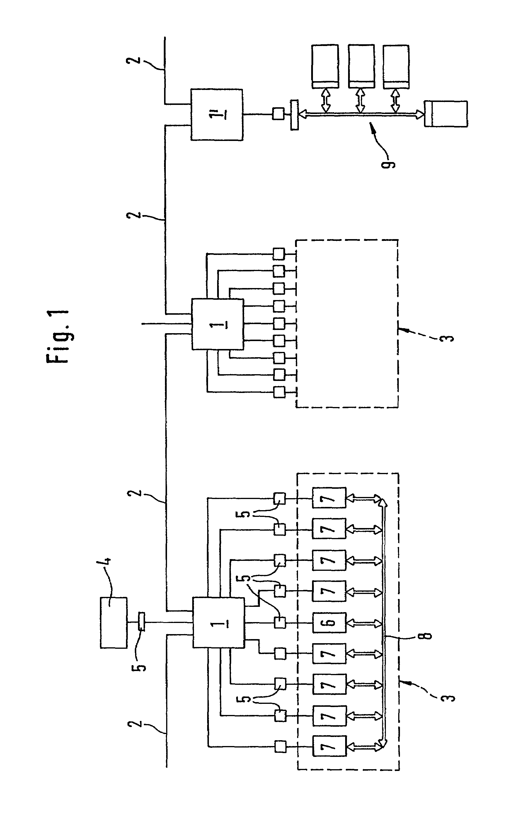
[0024]According to FIG. 1, a number of hub switches 1 are linked together, for example via fiber-optic cable 2. These hub switches 1 have a number of terminals which, on one hand, serve the fiber-optic cable 2 serving to link the hub switches and, on the other hand, serve for the modules of a programmable controller 3 and / or for a programming device 4.

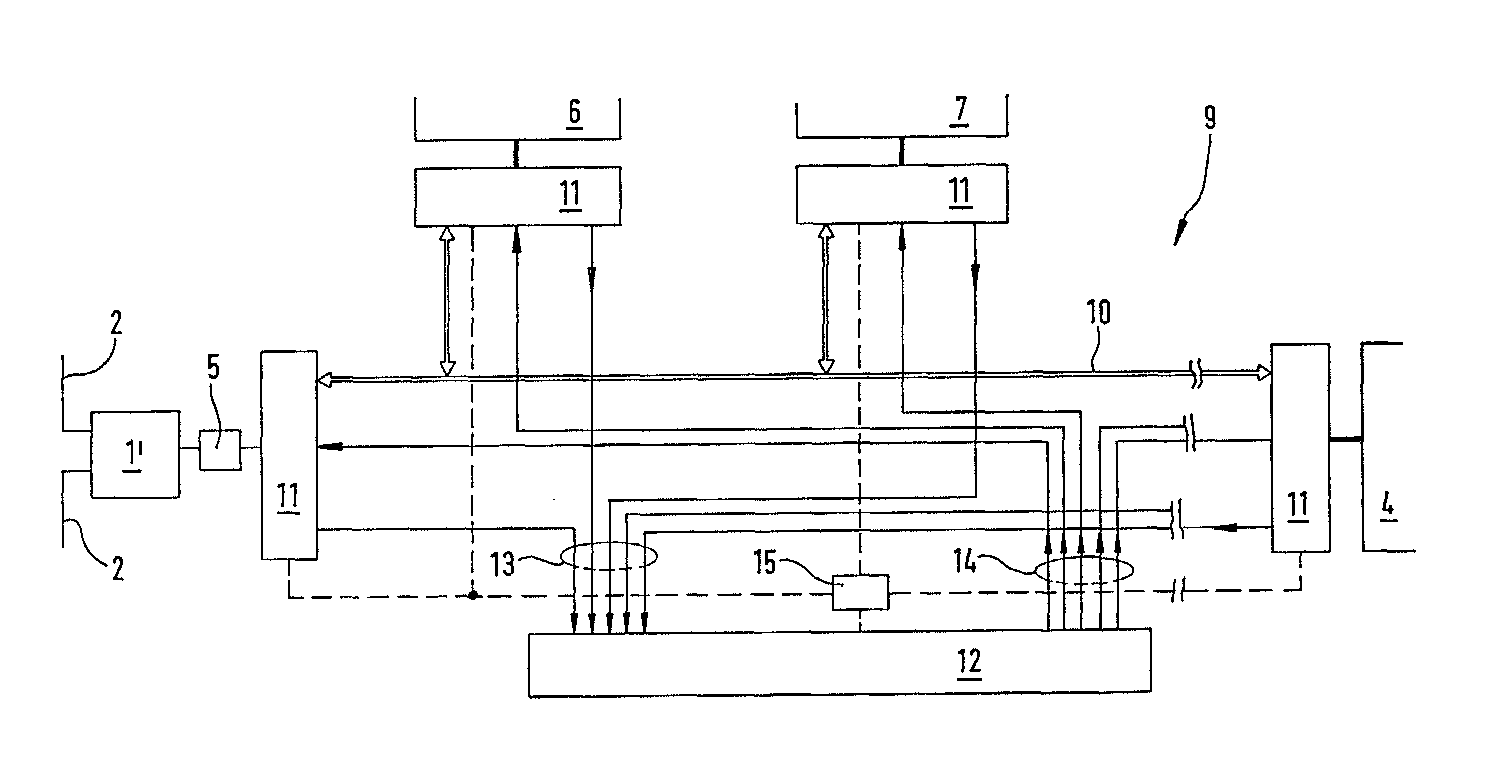
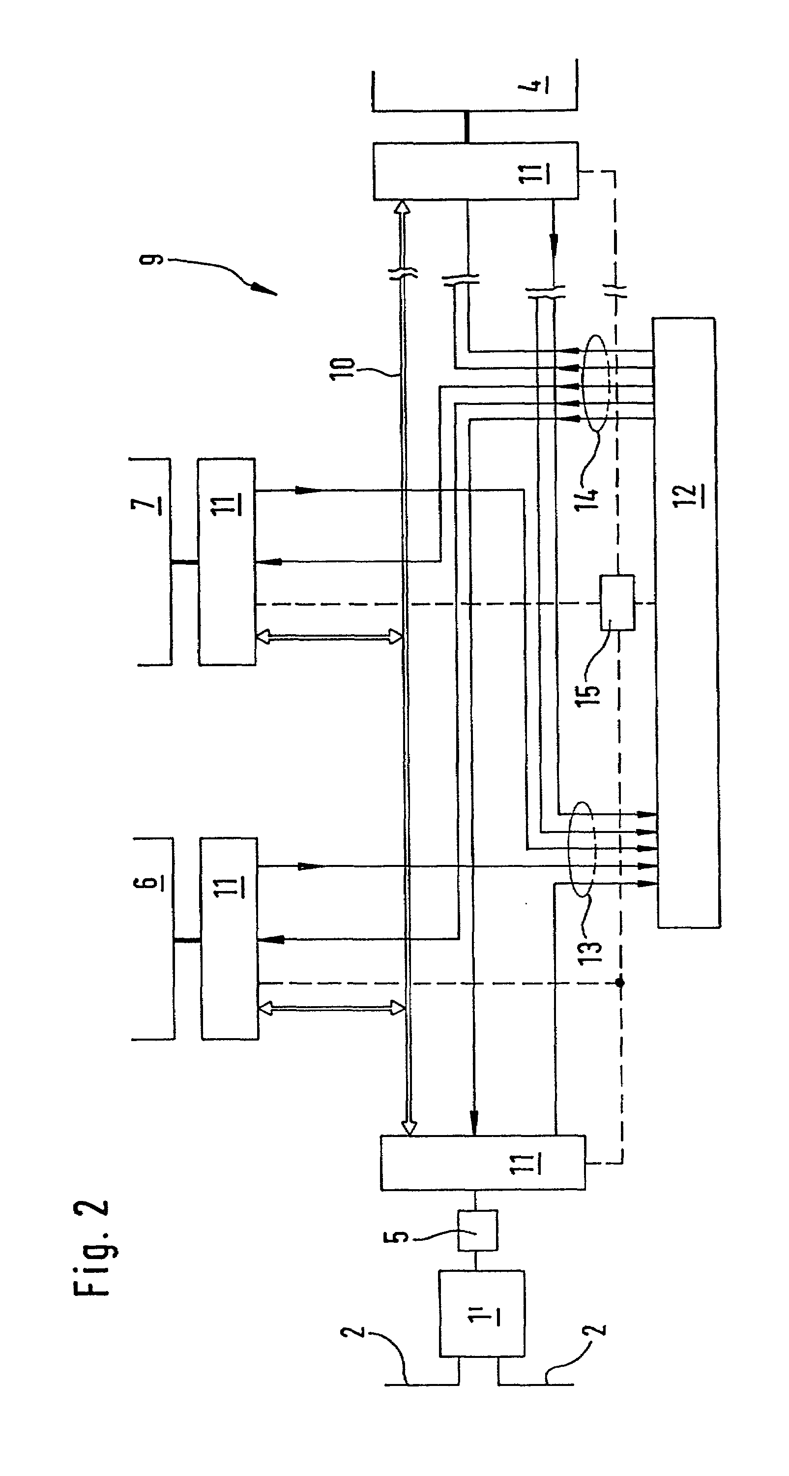
[0025]Insofar as the hub switches 1 are provided for other types of signals, optical signals in the present example, than the units to be coupled to the terminals of the hub switches, which could, for example, be provided for processing of electrical signals, appropriate interfaces and / or interface modules 5 are located and / or integrated in the hub switches 1 or the connected modules 6 and 7.

[0026]The hub switches 1 can separately store data entering their terminals and relay it via another terminal, which leads to the desired receiver for the data previously mentioned, with this relay only and / or first occurring when the previously me...


PUM


Abstract

Novel configuration preventing collision of data transmissions on data transmission paths. Repeated transmission attempts after said collisions thus become unnecessary. Transmission capacity of the data network can be used optimally resulting in considerably faster control.

Description

CROSS REFERENCE TO RELATED APPLICATIONS[0001]Applicants claim priority under 35 U.S.C. §119 of German Application No. 198 45 876.2 filed Oct. 6, 1998. Applicants also claim priority under 35 U.S.C. §365 of PCT / EP99 / 07345 filed Oct. 4, 1999. The international application under PCT article 21(2) was not published in English.BACKGROUND OF THE INVENTION[0002]1. Field of the Invention[0003]The invention concerns a network for data transmission with modules linked together for data exchange and hub switches, each with several terminals and assigned and / or integrated memory array, with each hub switch connecting its terminals in pairs while disconnecting from all other terminals and / or temporarily storing the data packets forwarded via the terminals separately and only forwarding them to the respective address terminal when it is available for data reception and / or can be disconnected.[0004]2. The Prior Art[0005]These types of networks are known in principle in the field of communication n...

Claims


Application Information

Patent Timeline
IPC IPC(8): G06F15/16G06F13/00G05B15/02G05B19/05H04L12/40H04L12/46
CPCG05B19/052
Inventor BOHRINGER, HARALDKAISER, STEFANKRAUT, ANDREASNEHR, WALTERSCHWIPS, STEFFEN
Owner JETTER AG
Why Eureka
Eureka Blog
Learn More