
Beam laser atmospheric scattering trajectory guidance

a beam laser and atmospheric scattering technology, applied in the direction of direction controllers, weapons, weapons types, etc., can solve the problems of high cost of precision, high cost of seeker components such as gimbals, domes, high-performance electronics and software, etc., and achieve the effect of less costly implementation

Inactive Publication Date: 2006-12-19
HER MAJESTY THE QUEEN AS REPRESENTED BY THE MINIST OF NAT DEFENCE OF HER MAJESTYS CANADIAN GOVERNMENT
View PDF9 Cites 1 Cited by
  • Summary
  • Abstract
  • Description
  • Claims
  • Application Information

AI Technical Summary

Benefits of technology

This approach provides precise, low-cost guidance that is immune to countermeasures and compatible with highly profiled nose designs, reducing operational costs and enhancing missile accuracy.

Problems solved by technology

The required precision has high costs due, in great part, to the complexity of the guidance techniques generally used.
The problem with these approaches is the high costs associated with seeker components such as gimbals, domes, high performance electronics and software.
This guidance system does not have any sensor directed toward the target and this limits what type of countermeasures may be effective.
The majority of guidance techniques, other than those taught by McCowan et al and Walter E. Miller Jr., share a common weakness in that they are susceptible to detection by the target which can employ countermeasure since the field-of-view of their guidance sensor have to continuously look at the target.
Countermeasure that may be employed including dazzling or destruction of the sensor which would ruin the precision guidance of the missile.
The majority of these missiles still rely on complex and costly gyroscopes and accelerometers to assist in guidance.
A new generation of hypervelocity missiles presently being developed inevitably call for a highly profiled fuselage nose that denies any possibility of using a forward-looking sensor because that would require a dome at the tip of the missile.

Method used


Image

  • Beam laser atmospheric scattering trajectory guidance
  • Beam laser atmospheric scattering trajectory guidance
  • Beam laser atmospheric scattering trajectory guidance

Examples


Embodiment Construction

[0018]Precision guidance for missiles is a subject of high interest for all military organizations throughout the world. The required precision has high costs due, in great part, to the complexity of the guidance techniques generally used. Radar, RF, GPS, TV, IR or lasers are examples of technologies that have been used to meet the guidance precision requirements. The majority of the present approaches are based on terminal homing seekers. The problem with these approaches is the high costs associated with seeker components such as gimbals, domes, high performance electronics and software. Other techniques make use of a human in the loop to reduce the complexity and costs of the components installed aboard a missile. In these techniques, a human operator provides assistance to a missile's guidance system by correcting its trajectory through a data link such that a satisfactory trajectory of the missile to the target is achieved. This approach substantially reduces the costs of the g...


PUM


Abstract

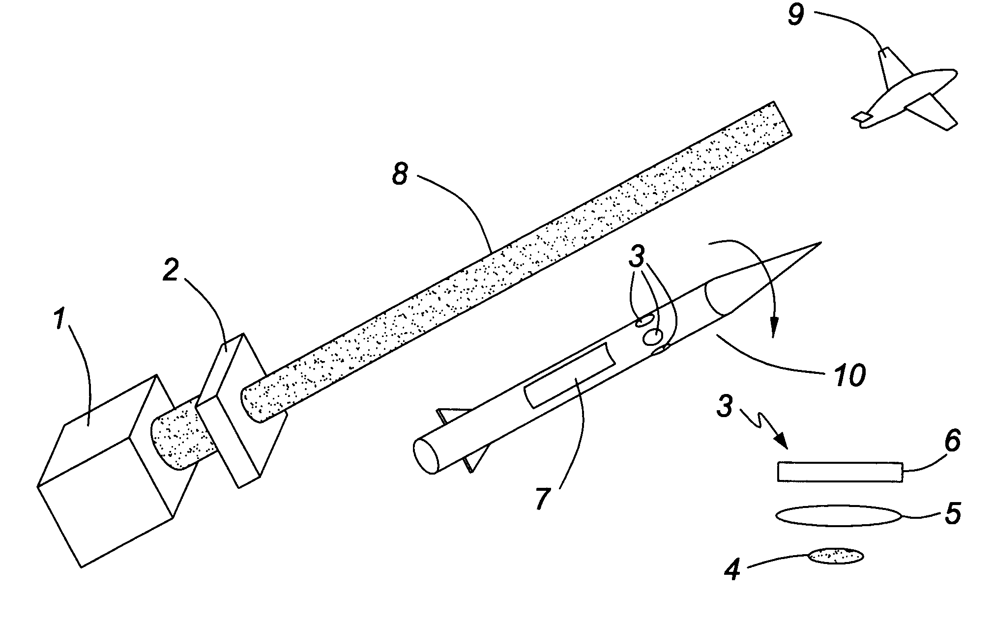
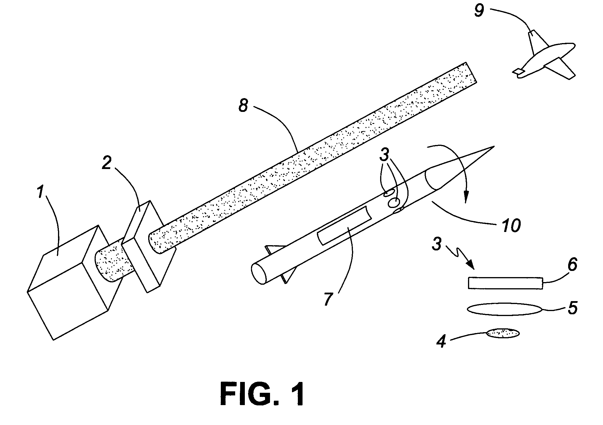
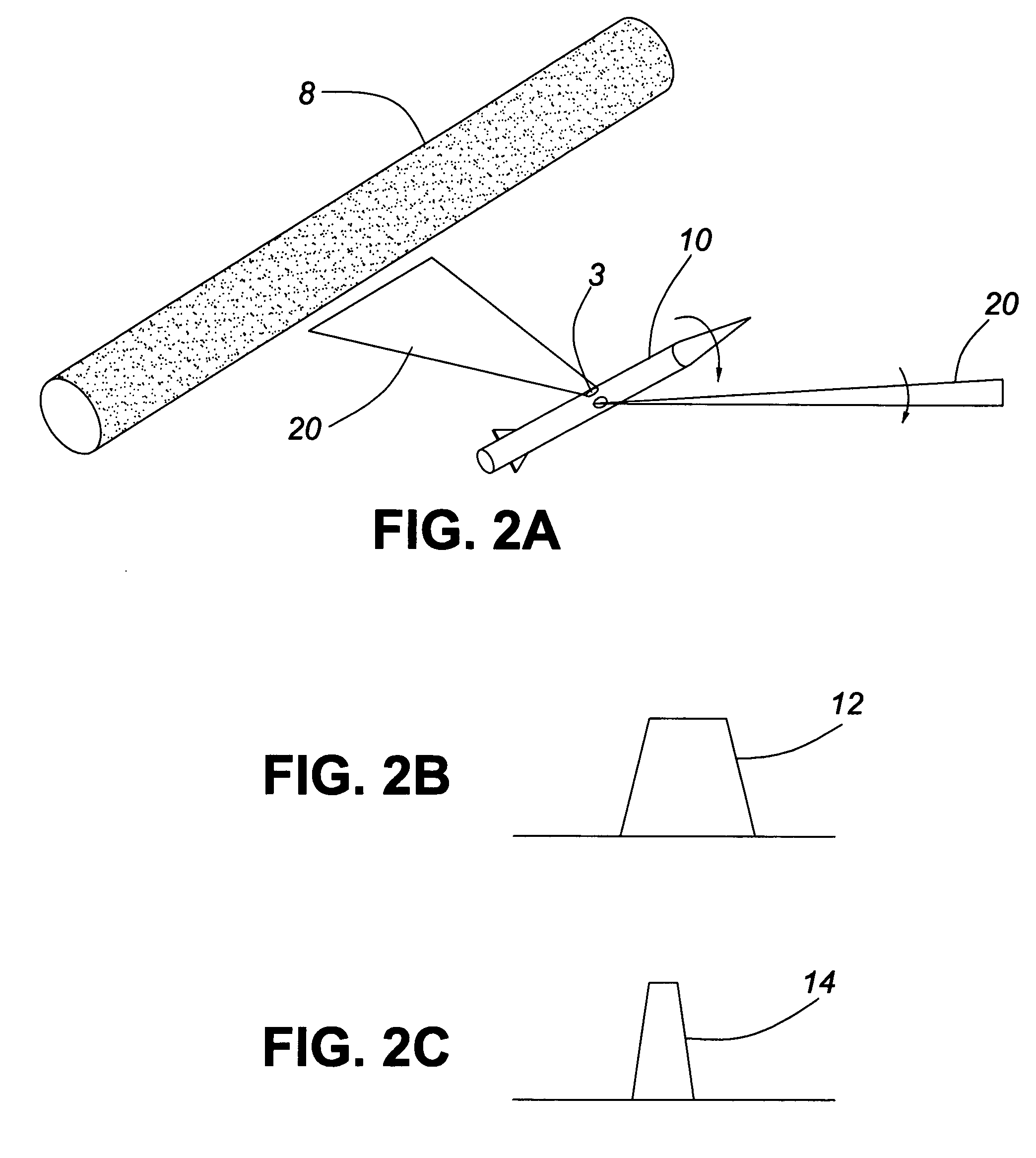
A guidance system for a missile utilitizes a laser beam source at a missile launch pad to generate a laser beam that is directed towards a target. A sensor on the body of a spinning missile detects radiation scattered from the laser beam, the sensor looking sideways and backward at an angle to the missile's longitudinal axis. Signals generated by that sensor are applied to a missile's guidance system's processing electronics that then determines the distance from the missile to the beam from the width of the signal generated by the sensor due to detecting scattered radiation from that laser beam. Once the distance between the missile and the beam is determined, the missile's guidance system corrects the missile's trajectory to maintain its position at a predetermined distance from the beam.

Description

FIELD OF THE INVENTION[0001]The present invention relates to a missile guidance system and in, particular, to a system where sensors on the missile detect light scattered from a laser beam directed towards a target, signals generated by the sensors being applied to processing electronics in the missile that determines, from the signals, the distance the missile is from the beam and then provides guidance signals to the missile's guidance system to maintain the missile's trajectory at a predetermined position with respect to the laser beam.BACKGROUND OF THE INVENTION[0002]Precision guidance for missiles is a subject of high interest for all military organizations throughout the world. The required precision has high costs due, in great part, to the complexity of the guidance techniques generally used. Radar, RF, GPS, TV, IR or lasers are examples of technologies that have been used to meet the guidance precision requirements. The majority of the present approaches are based on termin...

Claims


Application Information

Patent Timeline
Patent Type & Authority Patents(United States)
IPC IPC(8): F41G7/26F41G7/24F41G7/00
CPCF41G7/26
Inventor DUBOIS, JACQUESFORTIN, JEAN
Owner HER MAJESTY THE QUEEN AS REPRESENTED BY THE MINIST OF NAT DEFENCE OF HER MAJESTYS CANADIAN GOVERNMENT
Learn More