

Optical device
a technology of optical devices and ferrules, applied in the field of optical devices, can solve the problems of large insertion loss, complicated structure, and increase the entire length, and achieve the effect of reducing the strength of the ferrule and low loss
- Summary
- Abstract
- Description
- Claims
- Application Information
AI Technical Summary
Benefits of technology
Problems solved by technology
Method used
Image

Examples
embodiment 1
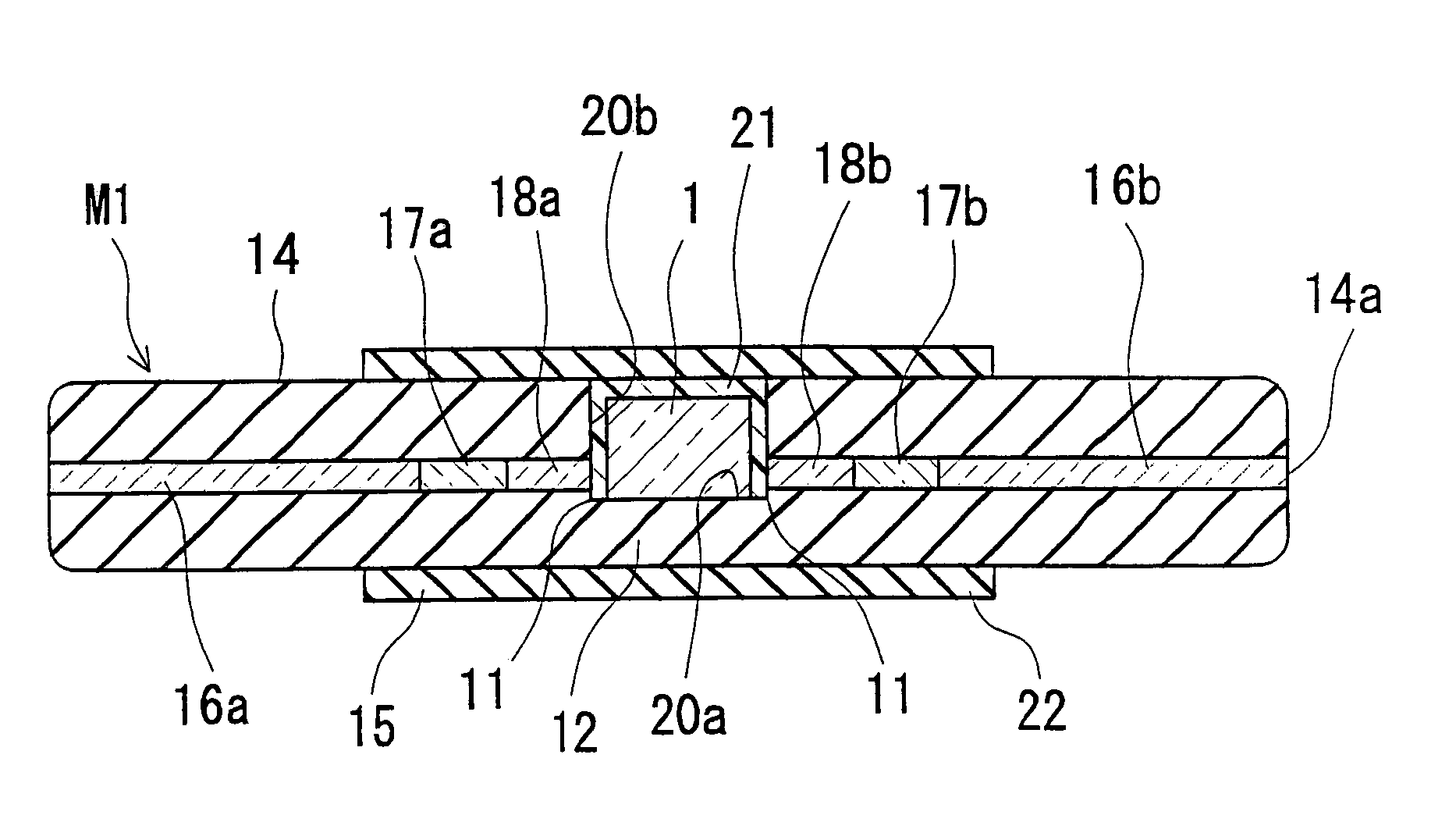
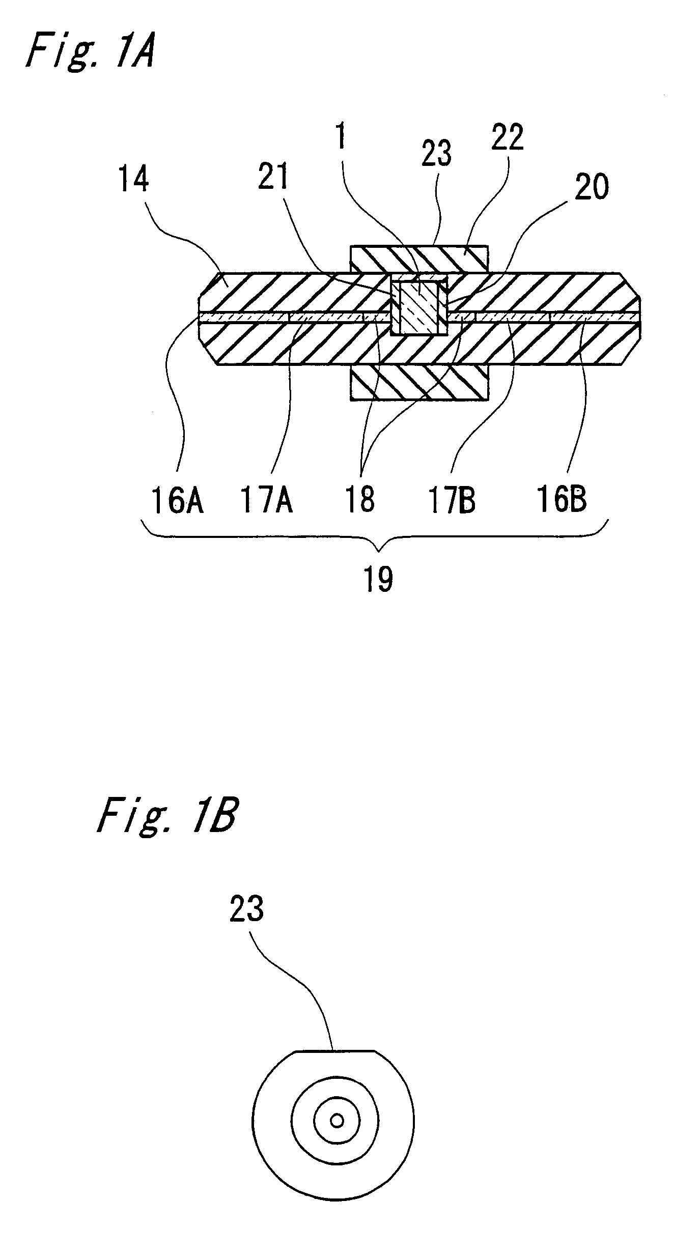
[0056]FIG. 1A is a cross-sectional diagram showing an optical device M1 according to Embodiment 1 of the present invention.
[0057]As shown in FIG. 1A, an optical fiber body 19 is inserted into a ferrule 14, and an optical isolator 1, which is an optical element, is placed within a recess 20 that has been created in the ferrule 14. The surrounding space of the optical isolator 1 is filled in with an adhesive 21. In addition, an annular reinforcing member (protective member) 22 is attached so as to surround the recess 20 in the ferrule 14.
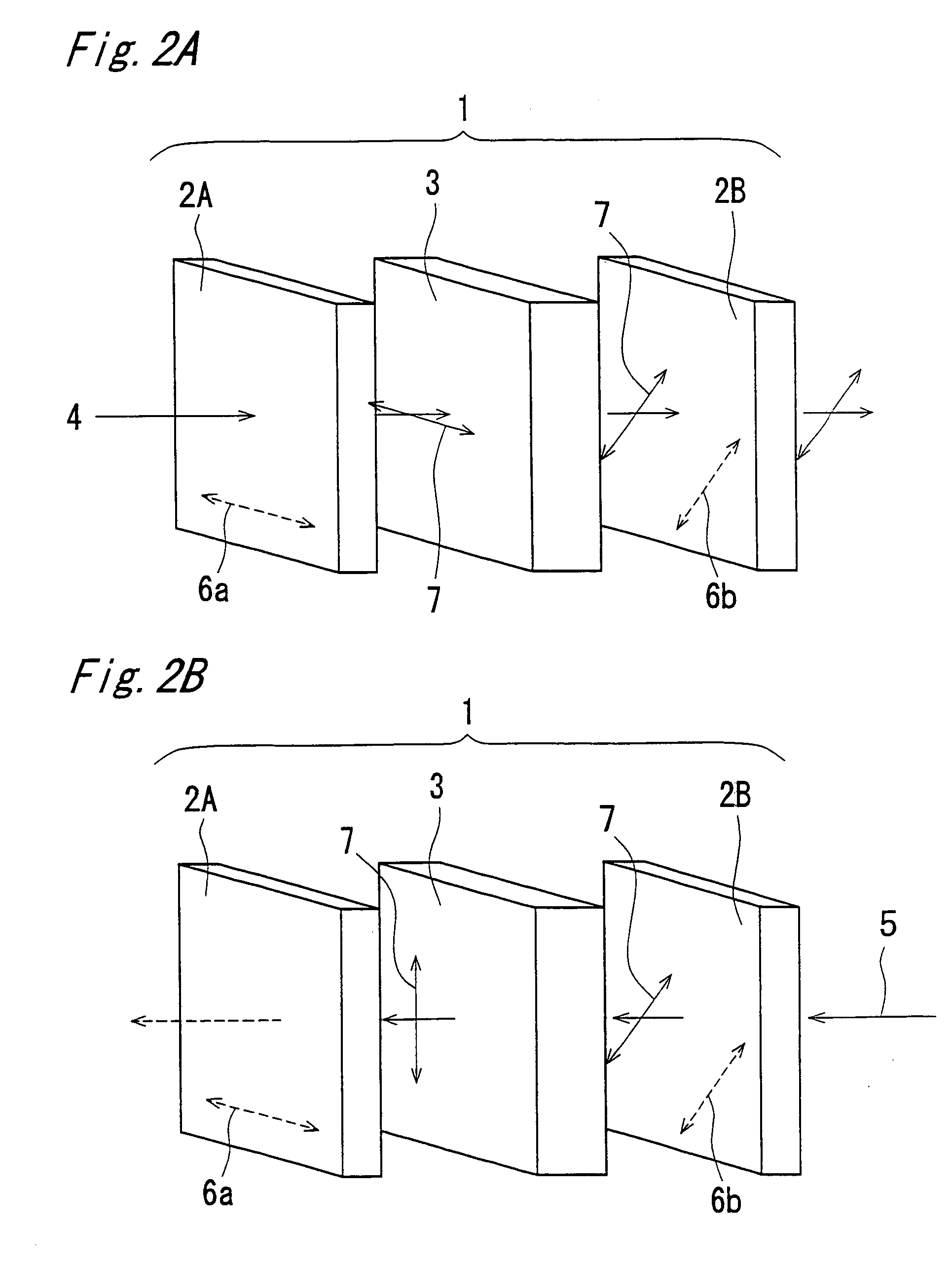
[0058]The optical isolator 1 has a function of transmitting light in the forward direction, and of blocking light in the backward direction. In a semiconductor laser (hereinafter abbreviated to LD) utilized for optical communication or optical measurement, the internal state of interference is nullified, causing problems such as a difference in the wavelength and fluctuation of the output when reflected light returns from the outside so as to enter th...
embodiment 2
[0081]FIGS. 15A to 19A and FIGS. 15B to 19B are cross-sectional diagrams and side diagrams showing the optical device according to Embodiment 2. In the present embodiment, a protrusion portion for restricting the rotation of the optical device around the optical axis is formed in the annular reinforcing member. The remaining portions are the same as those in Embodiment 1. In the present embodiment also, the rotation of the optical device M1 around the optical axis can be physically restricted by the above described protrusion portion 24, and thereby, the angle between the polarization axis of the optical isolator 1 and the direction of polarization of incident light can be extremely easily controlled.
[0082]FIGS. 15A and 15B show an example where a protrusion portion 24 of which the cross-section is in rectangular form is provided to the protective member 22. The protrusion portion 24 is formed so as to have a predetermined relationship with the polarization axis of the optical eleme...
embodiment 3
[0088]FIGS. 20A to 23A and FIGS. 20B to 23B are cross-sectional diagrams and side diagrams showing the optical device according to Embodiment 3. In the present embodiment, a trench portion 25 for restricting the rotation of the optical device around the optical axis is created in the annular reinforcing member. The remaining portions are the same as those in Embodiment 1. In the present embodiment also, the rotation of the optical device M1 around the optical axis is physically restricted by this trench portion 25, and thereby, the angle between the polarization axis of the optical isolator 1 and the direction of polarization of incident light can be extremely easily controlled.
[0089]FIGS. 20A and 20B show an example where the trench 25 of which the cross-section is in rectangular form is created in the protective member 22, from the external peripheral surface. Trench 25 is created along the entire length of the protective member 22. The trench 25 is created so as to have a predete...
PUM
 Abstract
Description
Claims
Application Information