

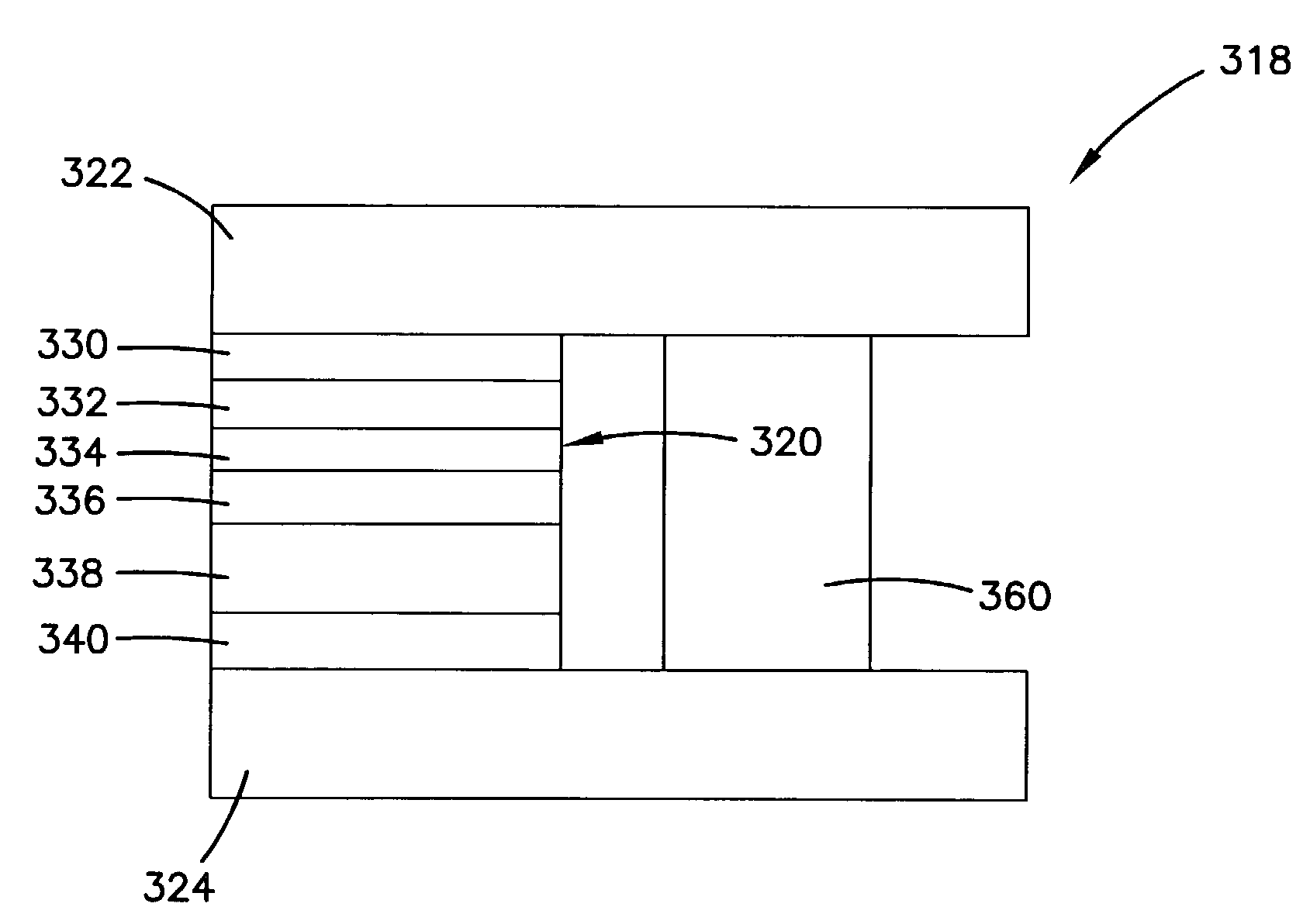
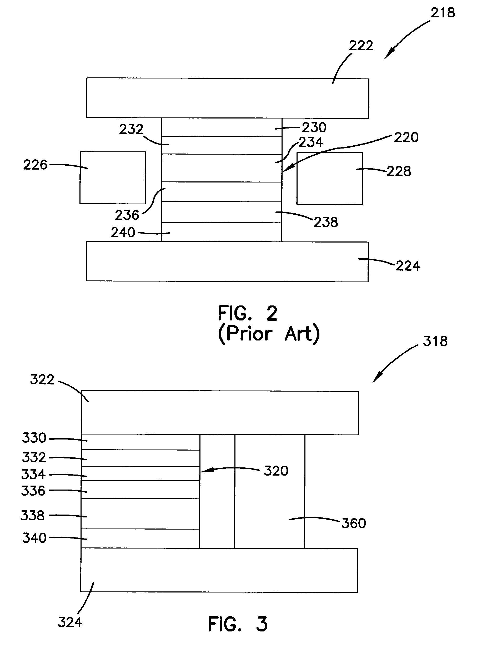
TMR head structure with conductive shunt
a tunneling magnetoresistive and read head technology, applied in the field of magnetic transducers, can solve the problems of reducing the effective resistance and magnetoresistance of the stack, the width of the sensor layer becomes an issue, and the spin valve is not well suited for high linear density applications, so as to reduce the effective resistance of the sensor, the effect of increasing the magnetoresistance and reliability of the sensor
- Summary
- Abstract
- Description
- Claims
- Application Information
AI Technical Summary
Benefits of technology
Problems solved by technology
Method used
Image

Examples
Embodiment Construction
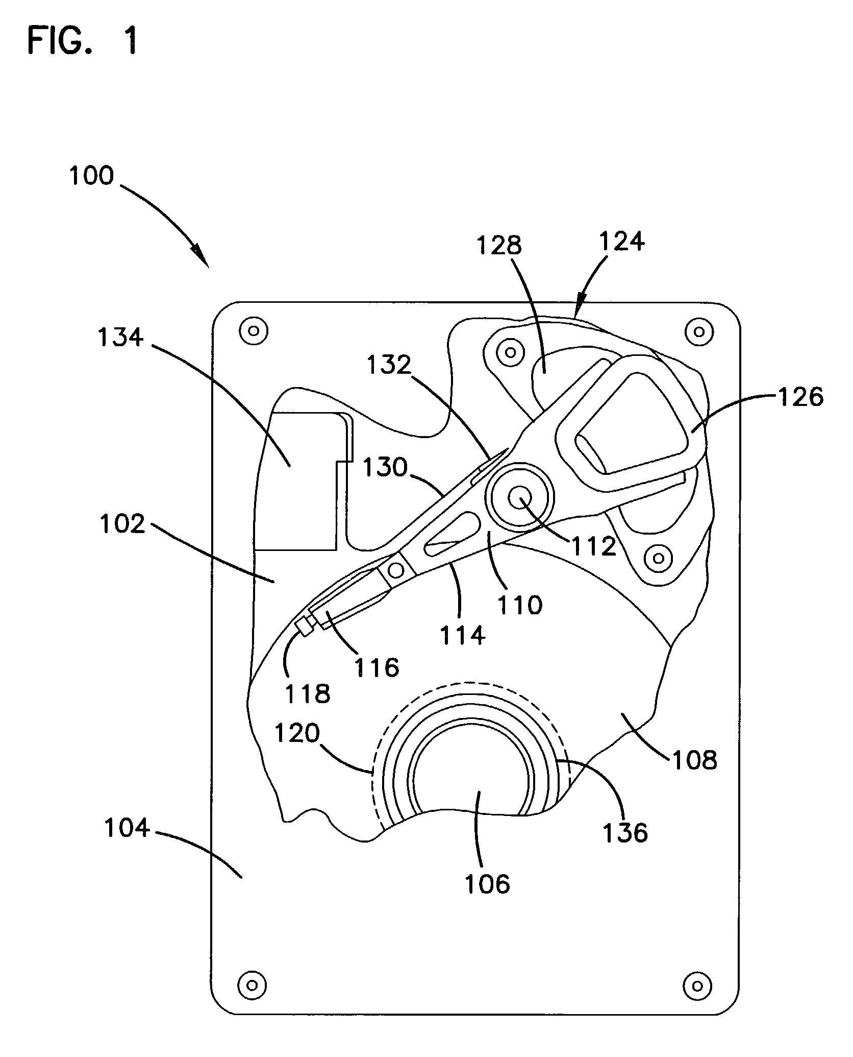
[0024]A disc drive 100 constructed in accordance with a preferred embodiment of the present invention is shown in FIG. 1. The disc drive 100 includes a base 102 to which various components of the disc drive 100 are mounted. A top cover 104, shown partially cut away, cooperates with the base 102 to form an internal, sealed environment for the disc drive in a conventional manner. The components include a spindle motor 106 which rotates one or more discs 108 at a constant high speed. Information is written to and read from tracks on the discs 108 through the use of an actuator assembly 110, which rotates during a seek operation about a bearing shaft assembly 112 positioned adjacent the discs 108. The actuator assembly 110 includes a plurality of actuator arms 114 which extend towards the discs 108, with one or more flexures 116 extending from each of the actuator arms 114. Mounted at the distal end of each of the flexures 116 is a head 118 which includes an air bearing slider enabling ...
PUM
| Property | Measurement | Unit |
|---|---|---|
| resistance | aaaaa | aaaaa |
| resistance | aaaaa | aaaaa |
| height | aaaaa | aaaaa |
Abstract
Description
Claims
Application Information