Laser processing device

a laser processing and laser technology, applied in the direction of optical elements, manufacturing tools, instruments, etc., can solve the problem of deviation of the beam spot position on the obj

Inactive Publication Date: 2006-12-19
FUJITSU LTD
View PDF15 Cites 31 Cited by
  • Summary
  • Abstract
  • Description
  • Claims
  • Application Information

AI Technical Summary

Benefits of technology

[0020]According to the above structure, it is possible to change the angle of divergence of the beam emitted from the emission surface of the optical fiber, by changing either the angle of divergence of the beam incident to the incidence surface of the optical fiber or the beam incident position on the incidence surface. Therefore, it is possible to change the diameter of the beam spot formed on an object to be processed, without changing the focal point of the condensing optical system.
[0021]As a result, it is not necessary to provide a special mechanism for changing a distance between the condensing lens and the object. Further, in the laser processing device using a galvano-scanner, it is not necessary to re-define the X-Y coordinates of a galvano-head each time when the diameter of the beam spot on the object to be processed is changed.

Problems solved by technology

(1) In order to change the diameter of the beam spot that is formed on the object to be processed, it is necessary to provide a special mechanism for changing the distance between the object to be processed and the condensing lens or the fθ lens.
(2) The fθ lens irradiates a beam onto the object approximately perpendicularly to the object, and slight error occurs at this time. When the distance between the object and the fθ lens is changed, there occurs a deviation in the position of the beam spot on the object.

Method used


Image

  • Laser processing device
  • Laser processing device
  • Laser processing device

Examples


first embodiment

[First Embodiment]

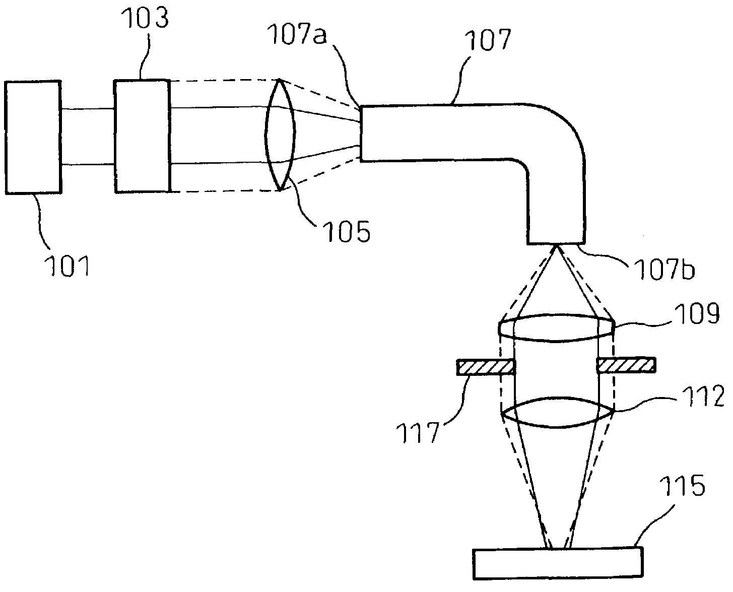
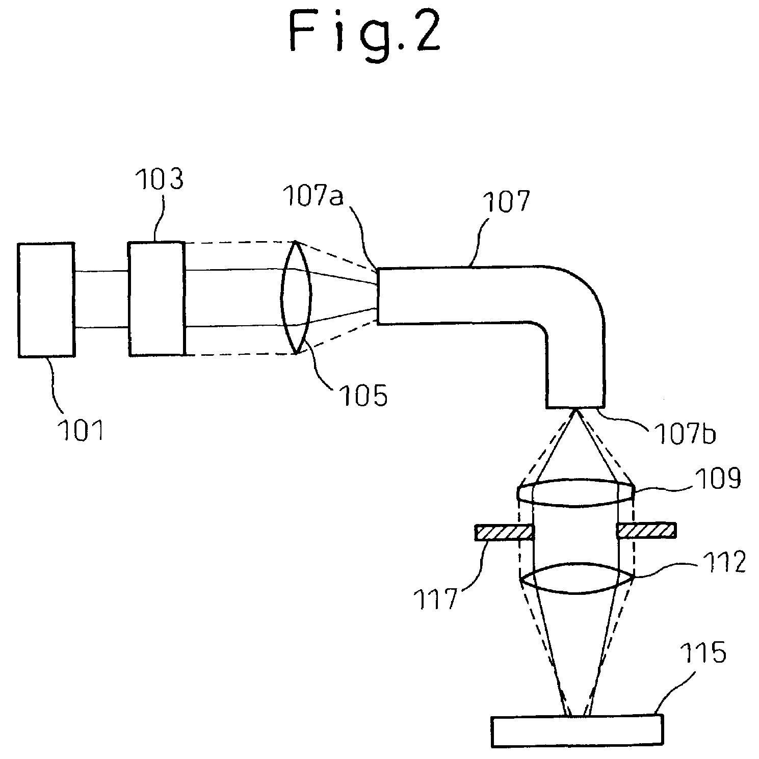
[0051]In FIG. 2, a YAG laser beam source 101 emits an approximately parallel beam to a beam expander 103 as an adjusting unit. In the present embodiment, the beam expander 103 is used to change the diameter of the emission beam.

[0052]A condensing lens 105 condenses the beam emitted from the beam expander 103, and makes the condensed beam incident to an optical fiber 107.

[0053]A collimator lens 109 of a condensing optical system sets the beam emitted from the optical fiber 107 into an approximately parallel beam. A condensing lens 112 of the condensing optical system condenses the parallel beam onto an object to be processed 15, thereby to carry out a spot welding.

[0054]When the diameter of the beam emitted from the beam expander 103 is changed from the diameter shown by a solid line to that shown by a broken line, the spot diameter of the beam on an incidence surface 107a of the optical fiber 107 condensed by the condensing lens 105 changes. In other words, the ang...

second embodiment

[Second Embodiment]

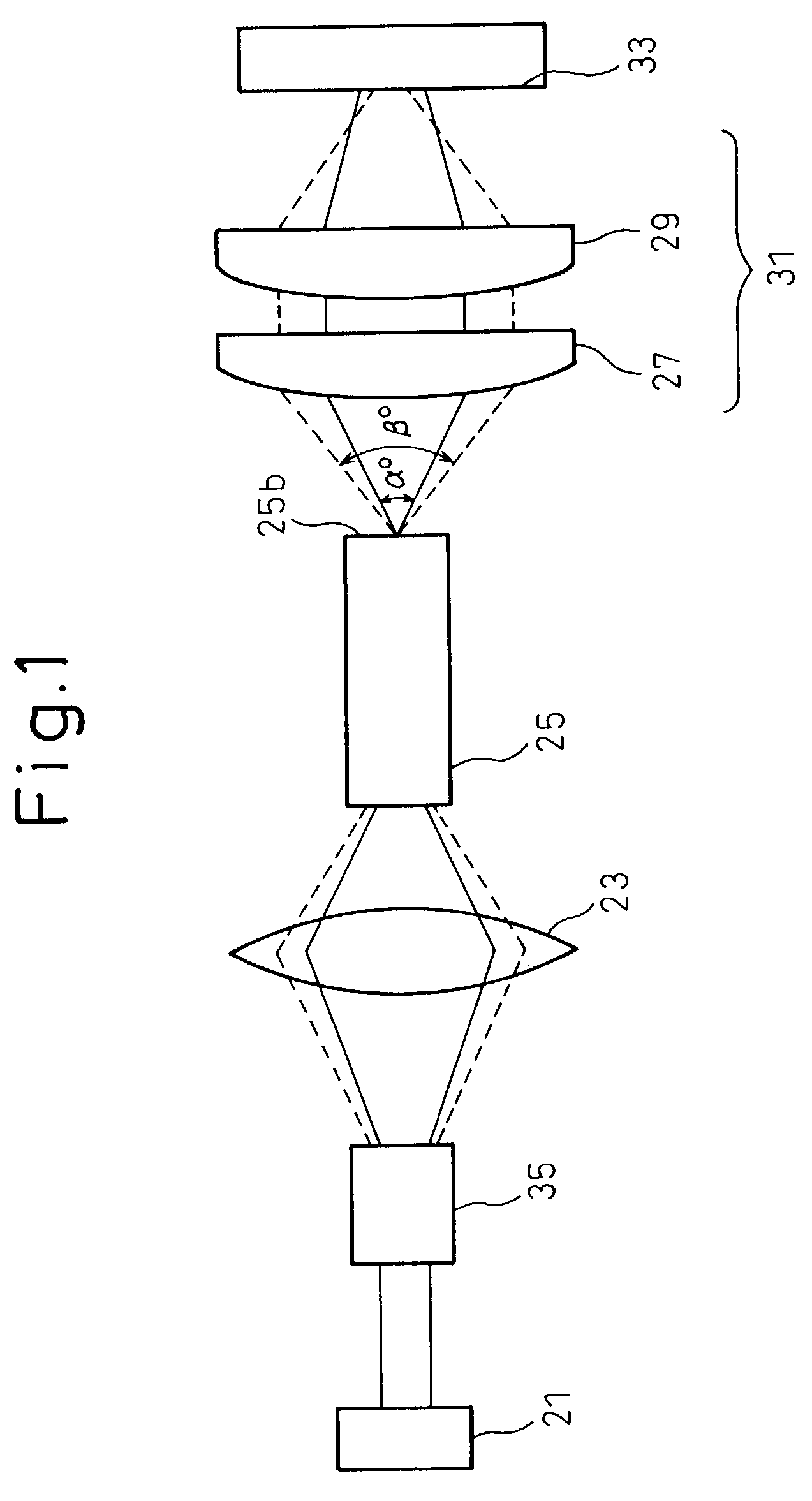
[0058]In FIG. 3, a YAG laser beam source 201 emits an approximately parallel beam to a beam expander 203 as an adjusting unit. In the present embodiment, the beam expander 203 is used to change the angle of divergence of the emission beam of the beam expander.

[0059]A condensing lens 205 condenses the beam emitted from the beam expander 203, and makes the condensed beam incident to an optical fiber 207.

[0060]A collimator lens 209 sets the beam emitted from the optical fiber 207 into an approximately parallel beam. A galvano-head 217 as a condensing optical system, that is, a galvano-scanner (a galvano-mirror) 211, reflects this parallel beam. A tele-centric type fθ lens 213 condenses the beam onto an object to be processed 215. A beam spot having a desired diameter is formed on the object to be processed 215, to thereby carry out spot welding.

[0061]Based on the scanning operation of the galvano-scanner 211 as the condensing optical system, the condensing position o...


PUM

PropertyMeasurementUnit
angle of divergenceaaaaaaaaaa
diameteraaaaaaaaaa
flexibilityaaaaaaaaaa

Abstract

The invention relates to a laser processing device that can change the diameter of a beam spot on an object to be processed, without using a mechanism for changing a distance between a condensing lens and the object. A beam emitted from a laser beam source is condensed by the condensing lens, and is made incident to an optical fiber. The beam emitted from the optical fiber is condensed by a condensing optical system onto an object to be processed. The object is welded using the condensed beam. The laser processing device comprises an adjusting unit that can change the angle of divergence of the beam on the emission surface of the optical fiber. The adjusting unit changes the angle of divergence of the beam, thereby to change the diameter of the beam spot formed on the surface of the object.

Description

BACKGROUND OF THE INVENTION[0001]1. Field of the Invention[0002]The present invention relates to a laser processing device that condenses a beam emitted from a laser beam source, makes the condensed beam incident to an optical fiber, condenses the beam emitted from the optical fiber onto an object to be processed by a condensing optical system, and finely processes the object.[0003]2. Description of the Related Art[0004]Conventionally, there have been developed various kinds of laser processing devices that condense a laser beam emitted from a laser beam source onto an object to be processed, and carry out fine processing of the object such as welding, perforation, and cutting, or irradiation processing of the object.[0005]To facilitate the utilization of this laser processing device, a laser micro-spot welding apparatus, for example, uses an optical fiber in the laser processing device for transmitting a laser beam, thereby to improve the flexibility in the structure of the device ...

Claims


Application Information

Patent Timeline
Patent Type & Authority Patents(United States)
IPC IPC(8): H01S3/10H01S3/08B23K26/06B23K26/064B23K26/073B23K26/21
CPCB23K26/073
Inventor IMAKADO, MASAYUKIMATSUSHITA, NAOHISA
Owner FUJITSU LTD
Why Eureka
Try Eureka