Methods of manufacturing a piezoelectric actuator and a liquid jetting head

a piezoelectric actuator and actuator technology, applied in the direction of positive displacement liquid engines, machines/engines, generators/motors, etc., can solve the problems of deteriorating efficiency of piezoelectric actuator manufacturing on an individual basis, insufficient piezoelectric element deformation efficiency, and inability to meet recent-growing demand. to achieve the effect of improving manufacturing efficiency

Inactive Publication Date: 2006-12-26
SEIKO EPSON CORP
View PDF15 Cites 31 Cited by
  • Summary
  • Abstract
  • Description
  • Claims
  • Application Information

AI Technical Summary

Benefits of technology

[0011]The present invention is conceived in view of the foregoing circumstances and aims at providing a method for manufacturing a piezoelectric actuator and a liquid ejecting head equipped with

Problems solved by technology

However, characteristics capable of responding to recently-growing demand cannot be achieved by mere use of the piezoelectric element of multilayer structure.
Various factors are conceivable as being responsible for this, including insufficient efficiency of deformation of the piezoelectric element.
For example, on the occasion of mass production of the piezoelectric actuator, manufacturing piezoelectric actuators on an individual basis deteriorates efficiency.
When the electro

Method used


Image

  • Methods of manufacturing a piezoelectric actuator and a liquid jetting head
  • Methods of manufacturing a piezoelectric actuator and a liquid jetting head
  • Methods of manufacturing a piezoelectric actuator and a liquid jetting head

Examples


Embodiment Construction

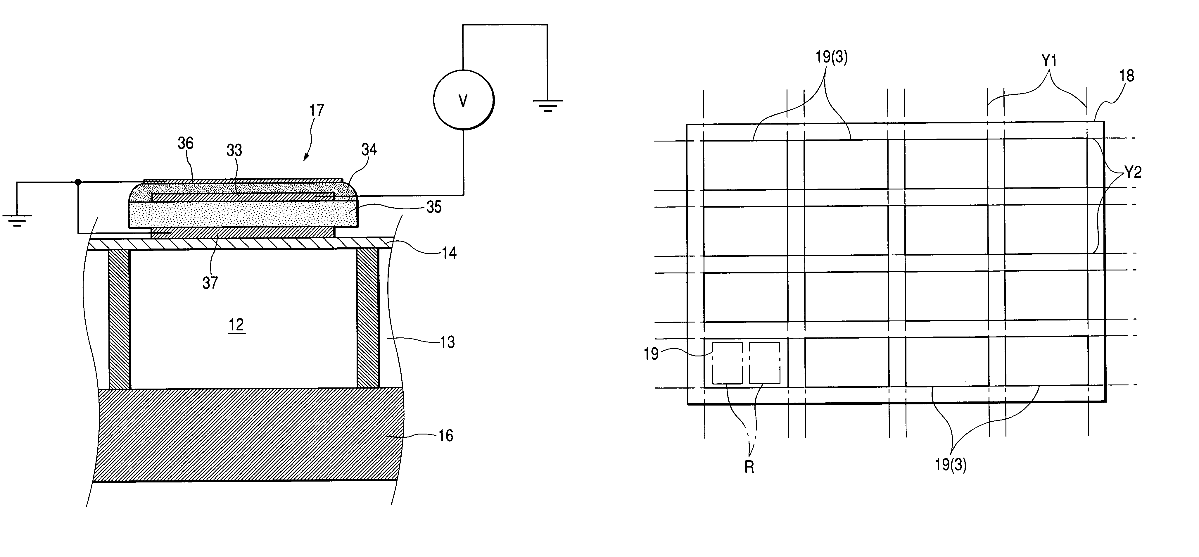
[0047]Embodiments of the invention will be described hereinbelow by reference to the accompanying drawings. Here, a liquid ejecting head will be described by taking, as an example, a recording head to be mounted on an image recording apparatus such as a printer or a plotter. As shown in FIG. 11, for example, the recording head has a plurality of head main bodies 1, and the head main bodies 1 are mounted on a mount base 61.

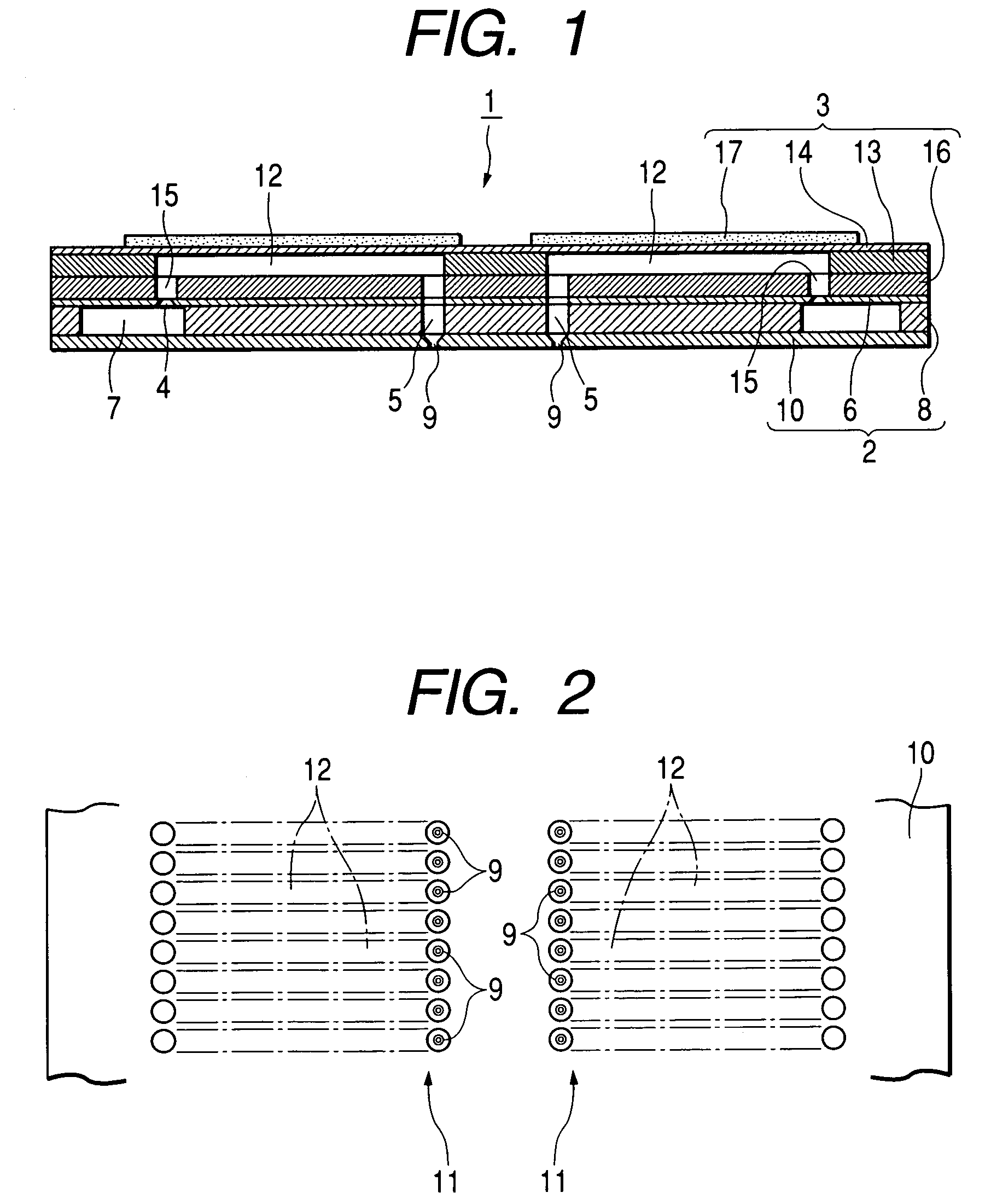
[0048]The basic structure of the head main body 1 will first be described by reference to FIGS. 1 and 2. The head main body 1 is essentially formed from a flow passage unit 2 and an actuator unit 3.

[0049]The flow passage unit 2 is fabricated from a supply port formation substrate 6 having formed therein through holes which are to serve as ink supply ports 4, and through holes which are to constitute portions of nozzle communication ports 5; a reservoir formation substrate 8 having formed therein through holes which are to serve as a common ink reservoir 7, and thro...


PUM

PropertyMeasurementUnit
Piezoelectricityaaaaaaaaaa

Abstract

Methods for manufacturing a piezoelectric actuator and a liquid ejecting head. In particular, a substrate, which is to be a vibration plate actuated by a piezoelectric element is prepared. A plurality of chip regions are defined on the substrate. A first common electrode of the piezoelectric element is formed on the substrate. A first piezoelectric layer of the piezoelectric element is formed on the first common electrode. A drive electrode of the piezoelectric element is formed on the first piezoelectric layer. A second piezoelectric layer of the piezoelectric element is formed on the drive electrode. A second common electrode of the piezoelectric element is formed on the second piezoelectric layer. Then, the substrate is cut so as to divide the chip regions from one another. In the aforementioned aspects of the invention, the first and second common electrodes as well as the drive electrode are formed so as not to extend beyond the outline of each of the chip regions.

Description

BACKGROUND OF THE INVENTION[0001]The invention relates to a method for manufacturing a piezoelectric actuator employing a piezoelectric element which becomes deformed upon receipt of a supplied drive signal, and to a liquid ejecting head equipped with the actuator, as well as to an actuator mother member from which the piezoelectric actuator is originated.[0002]A piezoelectric actuator is a member having a piezoelectric element which becomes deformed upon receipt of supplied electrical energy. The piezoelectric actuator is in widespread use as a drive element for, e.g., a liquid ejecting head, a micropump, and a sounding body (a speaker or the like). Here, the piezoelectric element is formed from piezoelectric ceramics made by compacting and sintering metal oxide powder, such as BaTiO3, PbZrO3, or PbTiO3, which are piezoelectric materials and exhibit a piezoelectric effect, or from a piezoelectric macromolecular film utilizing a high molecular compound.[0003]Here, the liquid ejectin...

Claims


Application Information

Patent Timeline
IPC IPC(8): H04R17/00B21D53/76B41J2/14B41J2/145B41J2/16F04B43/04H01L41/083H01L41/09H01L41/22H01L41/29H01L41/338H02N2/00
CPCB41J2/14233B41J2/161B41J2/1623B41J2/1632H01L41/0973B41J2002/14491Y10T29/49128Y10T29/49155Y10T29/49401Y10T29/49798Y10T29/49789Y10T29/42Y10T83/0524H10N30/2047
Inventor JUNHUA, CHANGKATAKURA, TAKAHIROOKUMURA, MOTONORI
Owner SEIKO EPSON CORP
Why Eureka
Try Eureka