
Transistor-arrangement, method for operating a transistor arrangement as a data storage element and method for producing a transistor-arrangement

a transistor arrangement and data storage technology, applied in the field of transistor arrangement, can solve the problems of increasing waste heat, affecting the development of increasingly smaller and more densely arranged transistors of hundreds of millions of transistors per chip, and affecting the performance of transistors, so as to achieve the highest possible storage density and the shortest possible signal propagation time

Inactive Publication Date: 2006-12-26
QIMONDA
View PDF13 Cites 16 Cited by
  • Summary
  • Abstract
  • Description
  • Claims
  • Application Information

AI Technical Summary

Benefits of technology

"The invention provides a transistor arrangement with a high storage density and stable operability in electronic components. The transistor arrangement includes a vertical transistor with a first electrode region, a second electrode region, a channel region, a gate region, and an electrically insulating layer sequence. The electrically insulating layer sequence has two sections that can store charge carriers, allowing for the storage of binary information. The transistor arrangement also has a stable operability in programming and erasure of the memory transistors, as well as a high storage density. The invention further includes a method for forming the transistor arrangement and a method for fabricating the transistor arrangement."

Problems solved by technology

Conventional silicon microelectronics will, however, encounter limits as miniaturization progresses further.
In particular, the development of increasingly smaller and more densely arranged transistors of hundreds of millions of transistors per chip will be subject to fundamental physical problems in the next ten years.
Moreover, the increasing integration density of the components on the chips leads to undesirable crosstalk between the components situated on the chips and to a dramatic increase in waste heat.
Further miniaturization is not possible by means of this arrangement.
This is disadvantageous with regard to the pursued aim of providing transistors having the highest possible storage density and also having the shortest possible signal propagation times.

Method used


Image

  • Transistor-arrangement, method for operating a transistor arrangement as a data storage element and method for producing a transistor-arrangement
  • Transistor-arrangement, method for operating a transistor arrangement as a data storage element and method for producing a transistor-arrangement
  • Transistor-arrangement, method for operating a transistor arrangement as a data storage element and method for producing a transistor-arrangement

Examples


Embodiment Construction

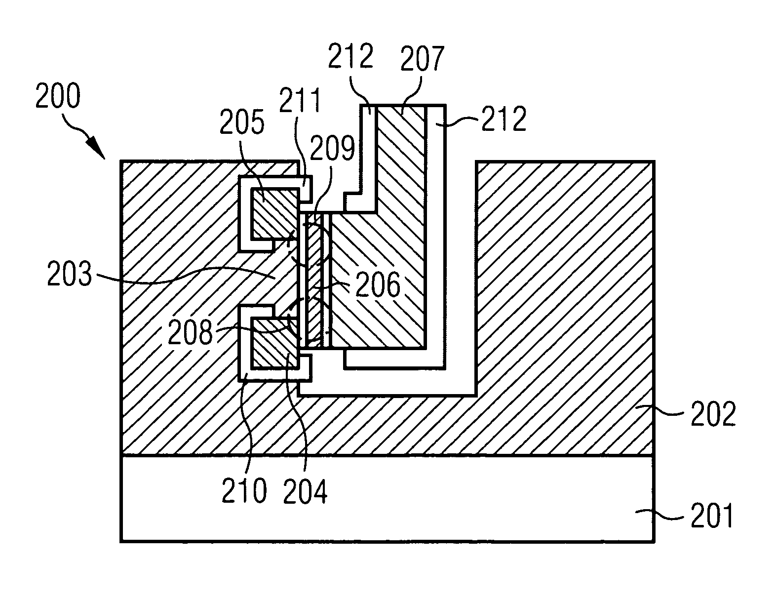
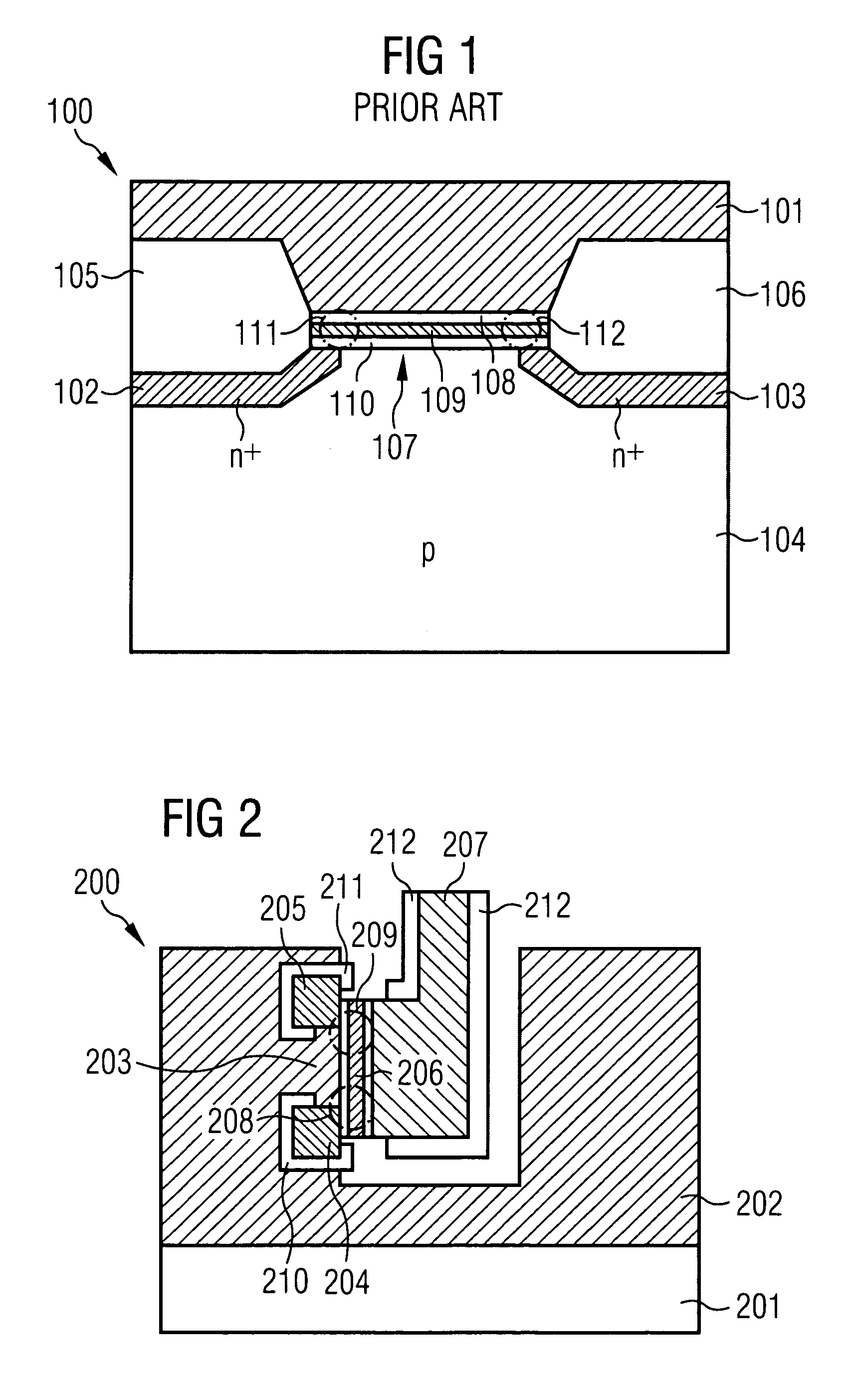
[0077]FIG. 2 shows a diagrammatic view of a transistor arrangement 200 in accordance with a first exemplary embodiment of the invention with a vertical transistor.

[0078]The transistor arrangement 200 has a substrate 201 and a channel layer 202—applied on the substrate 201—with a trench introduced therein, so that a channel region 203 is formed beside the trench. A vertical transistor is formed at the edge of the trench. The vertical transistor has a first electrode region 204 and a second electrode region 205, which are coupled to the channel region 203. In accordance with this exemplary embodiment, the first electrode region 204 is the source region and the second electrode region 205 is the drain region. Furthermore, the vertical transistor has an electrically insulating layer sequence 206, which extends between the first electrode region 204 and the second electrode region 205 along the channel region 203.

[0079]Moreover, the vertical transistor has an electrically conductive gate...


PUM


Abstract

The invention relates to a transistor arrangement having a substrate and a vertical transistor comprising: a first electrode region, a second electrode region arranged essentially above the latter, and, in between, a channel region, and also a gate region beside the channel region and, in between, an electrically insulating layer sequence, wherein two mutually spatially separate sections of the electrically insulating layer sequence in each case serve for the storage of charge carriers.

Description

CROSS-REFERENCE TO RELATED APPLICATION[0001]This application is a U.S. National-Stage entry under 35 U.S.C. § 371 based on International Application No. PCT / DE02 / 02263 filed Jun. 20, 2002, which was published under PCT Article 21(2); this application also claims priority under 35 U.S.C. § 119 to German Application No. 101 30 765.9 filed Jun. 26, 2001.BACKGROUND[0002]The invention relates to a transistor arrangement, a method for operating a transistor arrangement as a data memory and a method for fabricating a transistor arrangement.[0003]In view of the rapid ongoing development of computer technology, there is a need for storage media which provide ever-greater storage quantities on ever-smaller arrangements. Large quantities of data are usually stored in a large arrangement of memory cells. Memory cells used are, for example, nonvolatile memories which can store a stored information item for a long period of time without loss of information. An overview of nonvolatile memories is ...

Claims


Application Information

Patent Timeline
Patent Type & Authority Patents(United States)
IPC IPC(8): H01L27/108H01L29/76H01L29/788H01L29/94H10B12/00G11C11/56G11C16/04H01L21/336H01L21/8247H01L29/792H10B20/00H10B41/23H10B43/30H10B69/00
CPCG11C11/5671G11C16/0475H01L27/115H01L27/11553H01L27/11568H01L29/66833H01L29/7923H10B69/00H10B41/23H10B43/30H01L29/732
Inventor HOFMANN, FRANZWILLER, JOSEF
Owner QIMONDA
Learn More