
Integrated circuit delay chains

a delay chain and integrated circuit technology, applied in pulse generators, pulse manipulation, pulse techniques, etc., can solve problems such as reducing accuracy, chain circuits are susceptible to changes, and integrated circuits may not function properly

Inactive Publication Date: 2006-12-26
ALTERA CORP
View PDF11 Cites 26 Cited by
  • Summary
  • Abstract
  • Description
  • Claims
  • Application Information

AI Technical Summary

Benefits of technology

[0007]The delay chain circuitry has a number of delay chain stages. Each delay chain stage has a delay chain buffer such as a delay chain inverter and has an associated series-connected load resistance. A capacitor such as a non-gate-oxide capacitor is connected between ground and the input of each delay chain buffer.
[0008]The load resistors have associated load resistances. Load resistors may be formed using any suitable integrated circuit resistor structure. For example, the load resistors may be formed using polysilicon resistors or diffused resistors. To compensate for temperature-induced resistance changes in the load resistors, which would otherwise affect the RC delays of the delay chain stages and the overall delay of the delay chain, a temperature-...

Problems solved by technology

If a delay chain is too fast or too slow, signals passing through the chain will not be delayed by the desired amount and the integrated circuit may not function properly.
Conventional programmable logic device delay chain circuits are susceptible to changes induced by temperature fluctuations and process variations.
These sources of error reduce accuracy and make it difficult or impossible to use delay chain circuits effectively in many applications.

Method used


Image

  • Integrated circuit delay chains
  • Integrated circuit delay chains
  • Integrated circuit delay chains

Examples


Embodiment Construction

[0036]The present invention relates to arrangements that may be used to improve the accuracy of delay chain circuitry on integrated circuits. The invention applies to any suitable integrated circuits such as digital signal processors, microprocessors, application-specific integrated circuits, etc. For clarity, the present invention will sometimes be described in the context of digital integrated circuits such as programmable logic device integrated circuits. This is, however, merely illustrative.

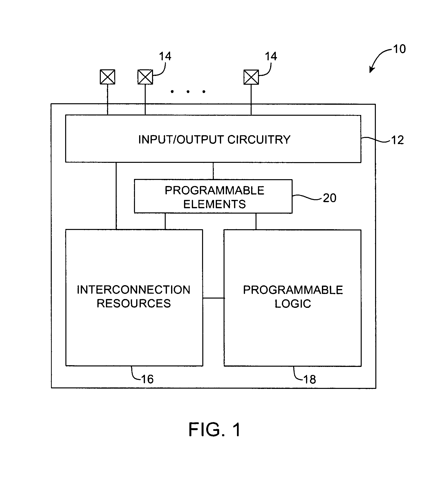
[0037]An illustrative programmable logic device 10 in accordance with the present invention is shown in FIG. 1.

[0038]Programmable logic device 10 may have input / output circuitry 12 for driving signals off of device 10 and for receiving signals from other devices via input / output pins 14. Interconnection resources 16 such as vertical and horizontal conductive lines may be used to route signals on device 10. Programmable logic 18 may include combinational and sequential logic circuitry. The pr...


PUM


Abstract

Delay chain circuitry is provided. The delay chain circuitry has a number of delay chain inverters. Each delay chain inverter is connected in series with a load resistor and has an associated capacitor between its input and ground. The electrodes of each capacitor may be formed from metal separated by non-gate-oxide dielectric to maintain accurate capacitor tolerances. A stable current source such as a bandgap reference current source may apply a current to a sensing resistor. The resulting bias voltage is indicative of changes in resistance due to changes in operating temperature. A temperature compensation circuit may use the bias voltage to produce temperature-compensation control signals. The temperature-compensation control signals are applied to the delay chain inverters to adjust their resistances and compensate for temperature-induced changes in the resistances of the load resistors. This ensures that the delay of the delay chain is independent of operating temperature.

Description

BACKGROUND OF THE INVENTION[0001]This invention relates to integrated circuits such as programmable logic device integrated circuits, and more particularly, to accurate delay chain circuitry for integrated circuits.[0002]Integrated circuits such as programmable logic devices often contain delay chain circuits for use in phase-locked loops, delay-locked loops, programmable delay circuits, input and output circuits, and other circuitry. A typical delay chain has a number of series-connected inverters. When a signal is applied to the input of the chain, it propagates though the inverters. Each inverter contributes a delay. The total delay of the chain is equal to the sum of the delays contributed by each inverter in the chain.[0003]The accuracy of delay chain circuits is often critical for satisfactory device performance. If a delay chain is too fast or too slow, signals passing through the chain will not be delayed by the desired amount and the integrated circuit may not function prop...

Claims


Application Information

Patent Timeline
IPC IPC(8): H03H11/26
CPCH03K5/133H03K2005/00039H03K2005/00058H03K2005/00143
Inventor MAANGAT, SIMARDEEPSHUMARAYEV, SERGEY Y.
Owner ALTERA CORP
Learn More