Clock generator and related biasing circuit

a clock generator and biasing circuit technology, applied in the direction of logic circuits, generating/distributing signals, pulse techniques, etc., can solve the problems of high accuracy and low noise of crystal oscillators, the cost of crystal oscillators is usually the significant part of the total cost of pll, and the clock generator cannot be replaced with any other common clock generator. , to achieve the effect of reducing the jitter of the utilized ico and reducing the cos

Active Publication Date: 2006-12-26
MEDIATEK INC
View PDF2 Cites 12 Cited by
  • Summary
  • Abstract
  • Description
  • Claims
  • Application Information

AI Technical Summary

Benefits of technology

[0009]It is an advantage of the present invention that the clock generator utilizes a biasing circuit for decreasing jitter of the utilized ICO. Hence the present invention clock generator does not have to utilize a crystal oscillator. Therefore the cost is reduced.
[0010]These and other objectives of the present invention will no doubt become obvious to those of ordinary skill in the art after reading the following detailed description of the preferred embodiment that is illustrated in the various figures and drawings.

Problems solved by technology

However, in every kind of PLL, for providing an accurate reference clock signal, the crystal oscillator cannot be replaced with any other common clock generator.
However, crystal oscillators of high accuracy and low noise are expensive.
No matter what category of the oscillator is utilized, the cost of the oscillator is usually the significant part of the cost of the total PLL.
Hence the effect of decreasing cost by simplifying or changing components other than the crystal oscillator is quite limited.
Still, utilizing oscillators other than crystal oscillators results in jitter generated by the flicker noise and thermal noise of the oscillation signals, which locate at low frequencies.
In video signal systems, the problem of jitter at low frequency is more serious since the jitter locates around the frequency of HSYNC signals.

Method used


Image

  • Clock generator and related biasing circuit
  • Clock generator and related biasing circuit
  • Clock generator and related biasing circuit

Examples


Embodiment Construction

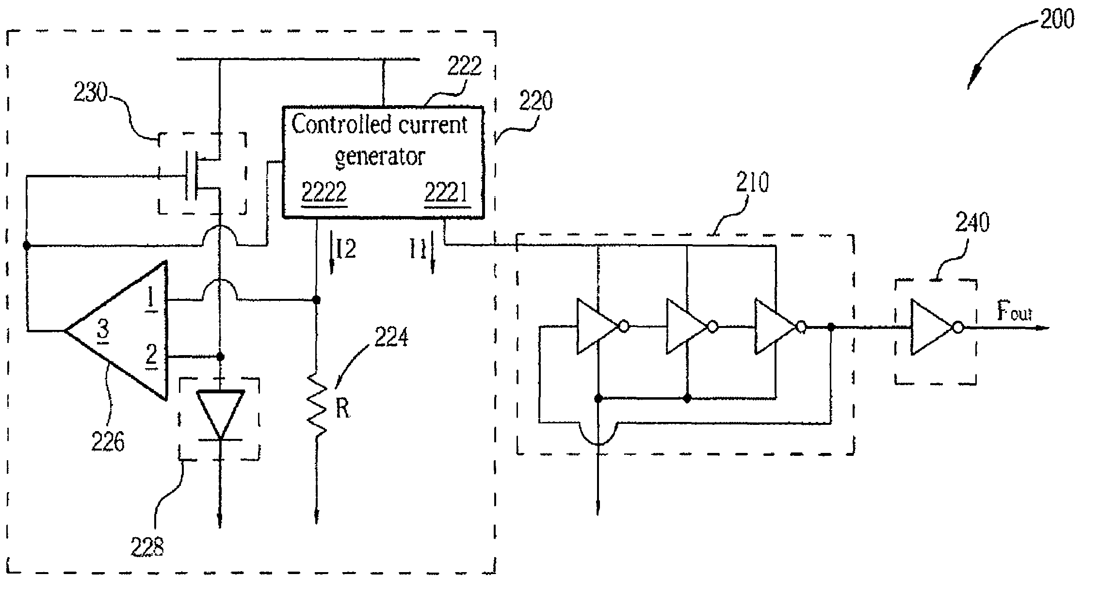
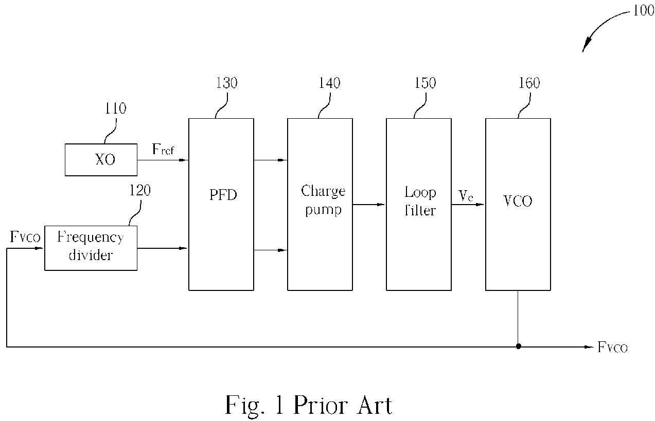
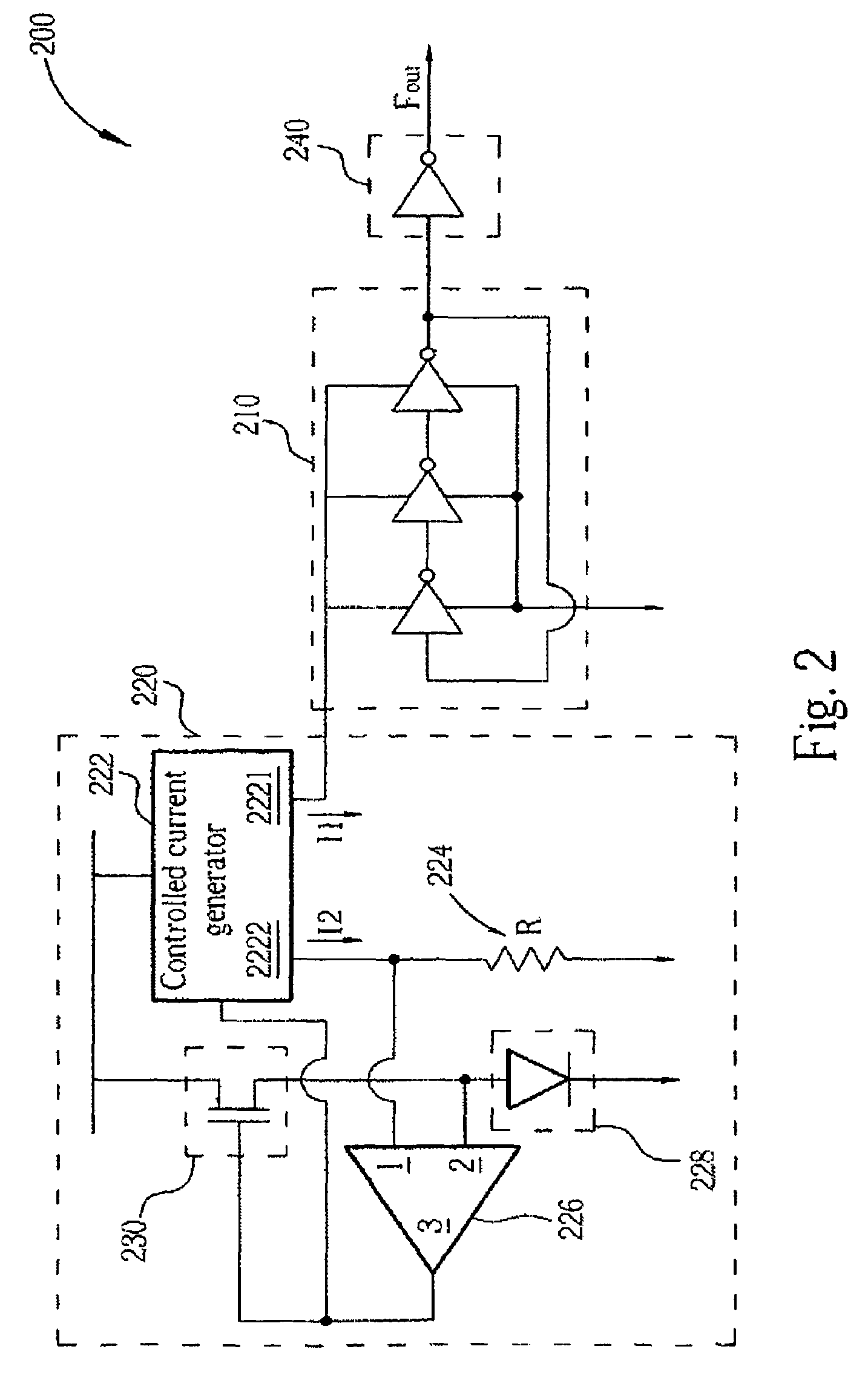
[0014]The present invention provides a clock generator including a common current-controlled oscillator (ICO) and a biasing circuit for providing reduced low-frequency jitter reference clock signals without the aid of any crystal oscillators. Conventionally, no matter of what structure the PLL is, a crystal is necessary for providing stable reference clock signals and hence generating an accurate and reduced low-frequency jitter output oscillation signals accordingly. However, in the present invention, the claimed clock generator and its adopted biasing circuit decrease the low-frequency jitter noise of the output reference clock signal. Hence the crystal oscillator can be replaced, and the cost is decreased in consequence.

[0015]The reason that the reference clock signals have to be generated by a crystal oscillator is that the current and voltages in most real circuits are inherently imprecise and unclear. For example, reference voltages generated by bandgap voltage generator commo...


PUM


Abstract

A clock generator capable of providing reduced low-frequency jitter clock signals without utilization of a crystal oscillator is introduced. The present invention clock generator utilizes a diode in related biasing circuit such that the generated control current to a current control oscillator is stable and clear due to the low flicker noise and low thermal noise of the voltage across the diode. The cost of PLL systems utilizing the present invention clock generator instead of a crystal oscillator is decreased. The adopted biasing circuit is introduced as well.

Description

CROSS REFERENCE TO RELATED APPLICATIONS[0001]The application claims the benefit of U.S. Provisional Application No. 60 / 517,076, filed Nov. 5, 2003, and included herein by reference.BACKGROUND OF INVENTION [0002]1. Field of the Invention[0003]The present invention generally relates to a clock generator and a biasing circuit adopted in the clock generator. More specifically, the present invention relates to a clock generator that provides stable clock signals without utilizing a crystal oscillator.[0004]2. Description of the Prior Art[0005]It is very important to provide stable clock signals in signal processing systems. Please refer to FIG. 1. FIG. 1 shows a block diagram of a prior art analog phase-locked loop 100. The analog phase-locked loop (PLL) 100 includes a crystal oscillator (XO) 110, a frequency divider 120, a phase-frequency detector (PFD) 130, a charge pump 140, a loop filter 150 and a voltage-controlled oscillator (VCO) 160. The analog PLL 100 utilizes the frequency divi...

Claims


Application Information

Patent Timeline
Patent Type & Authority Patents(United States)
IPC IPC(8): H03L1/00G06F1/04H03K3/011H03K3/03H03L1/02H03L7/08H03L7/099
CPCH03K3/011H03K3/0315H03L1/022H03L7/08
Inventor SMITH, STERLINGCHANG, HORNG-DER
Owner MEDIATEK INC
Why Eureka
Try Eureka