
Recording/reproducing separated type magnetic head having differential bias type magnetic domain control structure

a technology of magnetic domain control and separated type, applied in the field of recording/reproducing separated type magnetic heads, can solve the problems of increasing the frequency of the occurrence of heads with noise or waveform asymmetry, unable to increase the output while lowering unable to achieve the effect of reducing the longitudinal bias magnetic field, improving the output, and high sensitivity and stability

Inactive Publication Date: 2006-12-26
HITACHI GLOBAL STORAGE TECH JAPAN LTD
View PDF12 Cites 7 Cited by
  • Summary
  • Abstract
  • Description
  • Claims
  • Application Information

AI Technical Summary

Benefits of technology

[0012]The present invention intends to make improvement of the output and reduction of noises compatible and realize a magneto-resistive sensor of narrow track having high sensitivity and stability to provide a recording / reproducing separated type magnetic head device suitable for high density recording.
[0013]In order to attain the purpose described above, the invention provides a desired longitudinal bias capable of maintaining the longitudinal bias magnetic field higher at the end of a sensing portion and abruptly decaying the same toward the center of the sensing portion. Such longitudinal bias magnetic field described above can be attained by using a two-layered magnetic domain control layer. A first magnetic domain control layer plays a role identical with that of the existent hard bias layer, that is, it generates a longitudinal bias of directing the magnetization of the free layer to a predetermined direction. The second magnetic domain control layer generates a longitudinal bias magnetic field in the direction opposite to that of the first magnetic domain control layer. The first magnetic domain control layer is disposed near the free layer of the sensing portion while the second magnetic domain control layer is disposed slightly apart therefrom. The magnetic field distribution in the sensing portion is determined in accordance with the difference between both of the two magnetic domain control layers. By the provision of the hard bias magnetic field distribution, the output can be improved, as well as increase in the reproduction noises and fluctuation of the waveform asymmetry can be prevented.

Problems solved by technology

Further, since the gap Gs between the upper and lower shield layers changes scarcely while the track width has been narrowed recently, the longitudinal bias magnetic field remains even in the central portion of the track width of the sensing portion 2 as the case may be, making it difficult to improve the sensitivity.
Along with increase in the output, the frequency for the occurrence of heads having noises or waveform asymmetry is increased and it is actually impossible to increase the output while lowering the longitudinal bias magnetic field.
Accordingly, fixing for the magnetization at the track end becomes insufficient.
The problem includes reproduction noises and asymmetrical fluctuation of waveforms.
If it is intended to increase the output, noises increases, the waveform asymmetry is increased and the magnetic track width is enlarged, making it actually difficult to improve the output.
However, the subject cannot be attained in the existent hard bias structure.
In view of the above, this is attributable to that decrease of the longitudinal central bias magnetic field or decrease of the dead region for improving the output would lower the bias magnetic field at the end simultaneously and inevitably cause noises and waveform asymmetricity.

Method used


Image

  • Recording/reproducing separated type magnetic head having differential bias type magnetic domain control structure
  • Recording/reproducing separated type magnetic head having differential bias type magnetic domain control structure
  • Recording/reproducing separated type magnetic head having differential bias type magnetic domain control structure

Examples


embodiment 1

(Embodiment 1)

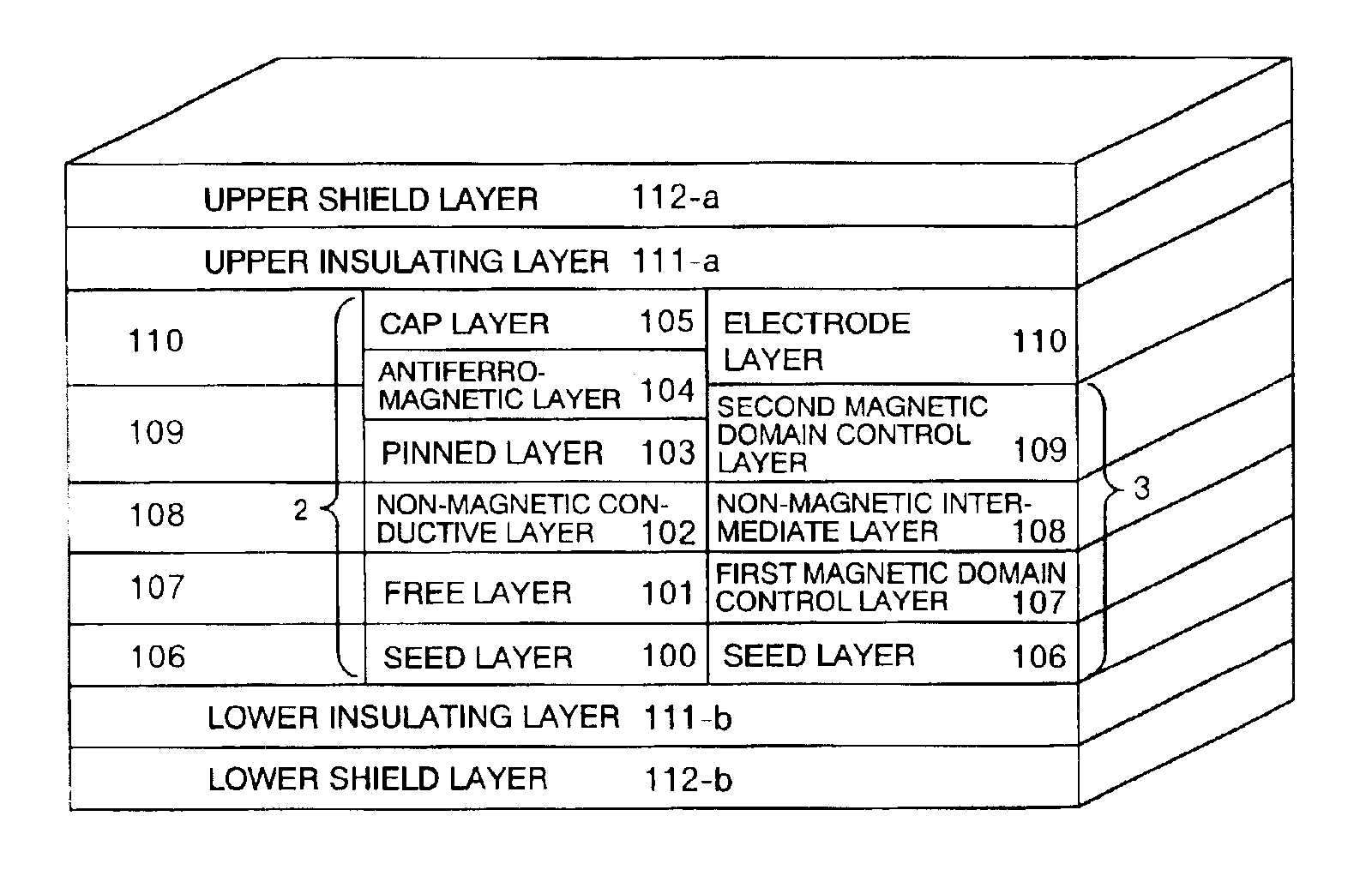
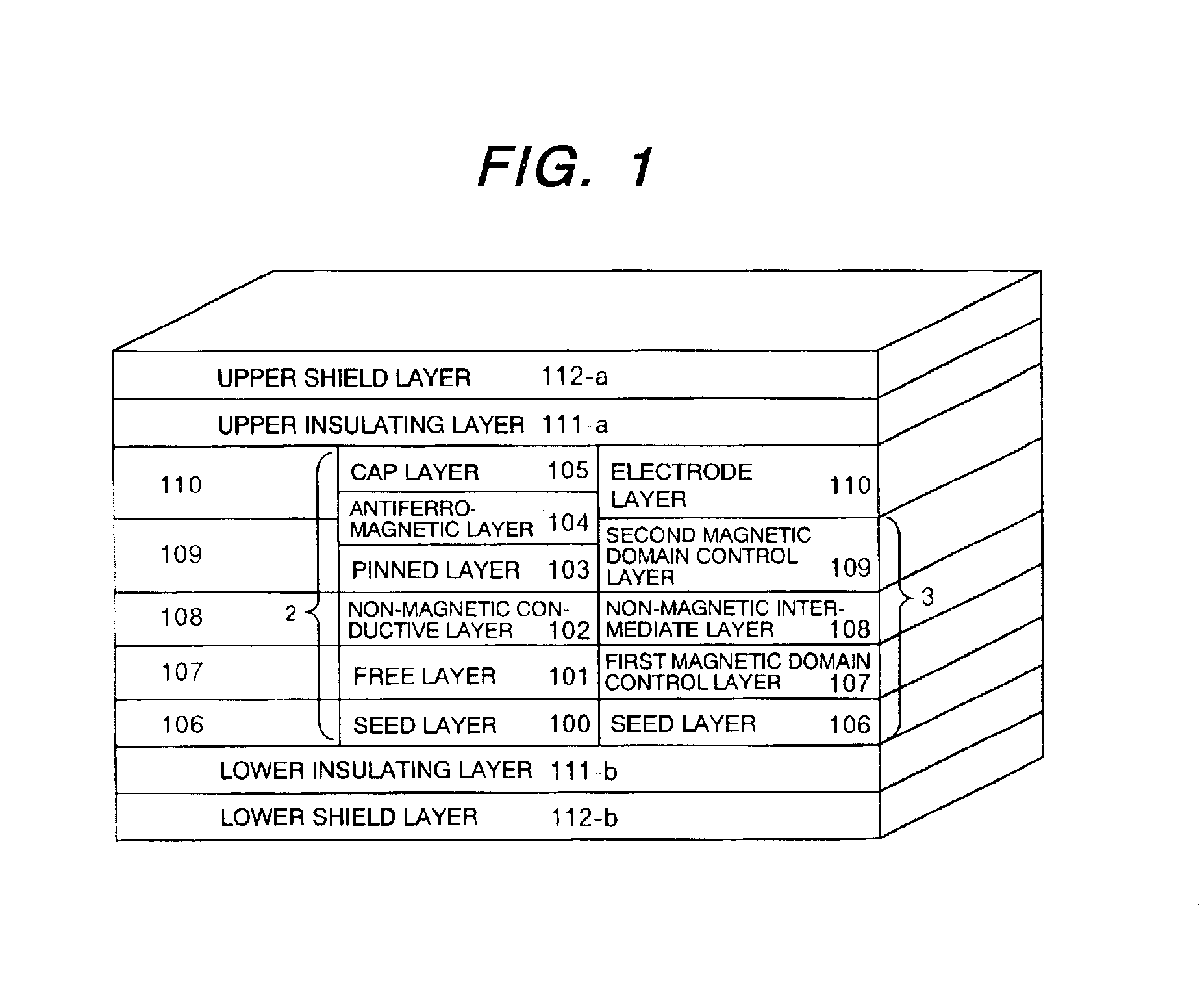
[0027]FIG. 1 shows a basic constitution of a magneto-resistive sensor according to a first embodiment of the invention. The magneto-resistive element (sensing portion) 2 has a constitution in which a seed layer 100, a free layer 101, a non-magnetic conductive layer 102, a pinned layer 103, an anti-ferromagnetic layer 104 and a cap layer 105 are stacked successively. The stacked film 2 is formed to have a predetermined width (track width), and stacks 3 each comprising a seed layer 106, a first magnetic domain control layer 107, a non-magnetic intermediate layer 108 and a second magnetic domain control layer 109, and electrode layers 110 are disposed at opposite ends of the stack 2. The constitution of the film material for the sensing portion 2 in this embodiment includes seed layer 100┌Ta 2 nm┘ / free layer 101┌NiFeCr 3 nm / NiFe 2 nm / CoFe 0.5 nm┘ / non-magnetic conductive layer 102┌Cu 2 nm┘ / pinned layer 103┌CoFe 2 nm / Ru 0.8 nm / CoFe 1.5 nm┘ / anti-ferromagnetic layer 104┌PtMn ...

embodiment 2

(Embodiment 2)

[0042]FIG. 7 shows a second embodiment of the invention. Provision of second magnetic domain control layers 109 on opposite sides of a spin valve film is effective for the decrease of the central magnetic field also even when applied to a magnetic domain control system of forming a first magnetic domain control layer 107 by stacking the spin valve as shown in FIG. 7. In this case, they are stacked as; spin valve film / cap layer Ru / first magnetic domain control layer ┌CoFe / IrMn(or PtMn)┘ and they are subjected to milling to have an identical track width. Since the magnetizing direction of CoFe in the upper portion is arranged in a certain direction due to IrMn (or PtMn) anti-ferromagnetic layer, it gives a strong magnetic field to a free layer 101 at the track end. That is, the CoFe / IrMn (or PtMn) layer plays a role as the first magnetic domain control layer 107. By disposing the second magnetic domain control layers 109 that generates a magnetic field in the opposite di...

embodiment 3

(Embodiment 3)

[0043]FIG. 8 shows a third embodiment in which the differential bias system is used for a tunneling magneto-resistive element (TMR). The layer constitution of the TMR element is similar with that of the spin valve element, in which an insulating layer (Al2O3) is used for a non-magnetic layer 102′ between a pinned layer 103 and a free layer 101. This is a reproducing element that utilizing a phenomenon that tunneling current changes depending on the difference of angle for the magnetizing direction between magnetic layers on both sides of the insulating layer 102′. In this embodiment, a seed layer 100, an anti-ferromagnetic layer 104, the pinned layer 103, the insulating layer 102′, the free layer 101 and a cap layer 105 are stacked in this order.

[0044]The tunneling current to the sensing portion is supplied through an upper electrode 110-a and a lower electrode 110-b disposed above and below the element. Magnetic domain control layers 3 are disposed at the outside of i...


PUM

PropertyMeasurementUnit
thicknessaaaaaaaaaa
thicknessaaaaaaaaaa
thicknessaaaaaaaaaa

Abstract

A recording / reproducing separated type magnetic head comprising a first magnetic domain control layer for arranging the magnetizing direction of a free layer included in a magneto-resistive element to a predetermined direction, and a second magnetic domain control layer for generating a magnetic field in the direction opposite thereto to constitute a differential type bias structure. The recording / reproducing separated type magnetic head decreases an excessively strengthened longitudinal bias magnetic field in a central portion at a narrow track width while avoiding decrease of the fixed magnetic field at the end of the magneto-resistive element in the direction of the track width.

Description

BACKGROUND OF THE INVENTION[0001]1. Field of the Invention[0002]The present invention relates to a recording / reproducing separated type magnetic head having a magneto-resistive sensor mounted thereon, the sensor utilizing the giant magneto-resistive (GMR) effect or the tuning magneto-resistive (TMR) effect.[0003]2. Description of the Prior Art[0004]FIG. 10 shows a basic constitution of a magneto-resistive sensor of an existent spin valve structure disclosed in Japanese Patent Laid-Open Hei 3-125311. In a spin valve structure (magneto-resistive effect element) 2, a free layer 101 having soft magnetic properties and a pinned layer 103 fixed for the magnetizing direction are stacked by way of a non-magnetic conductive layer 102 on a seed layer 100, an anti-ferromagnetic layer 104 is stacked on the pinned layer 103, and a cap layer 105 is disposed on the anti-ferromagnetic layer 104. The anti-ferromagnetic layer 104 serves to fix the magnetizing direction of the pinned layer 103. Furthe...

Claims


Application Information

Patent Timeline
Patent Type & Authority Patents(United States)
IPC IPC(8): G11B5/39G11B5/31H01F10/16H01F10/32H01L43/08
CPCB82Y10/00B82Y25/00G11B5/3909G11B5/3967G11B5/3116G11B5/313G11B5/3903G11B5/3932G11B2005/3996
Inventor FUKUI, HIROSHIOTOMO, SHIGEKAZUKOJIMA, SHUICHIKATAOKA, KOUJI
Owner HITACHI GLOBAL STORAGE TECH JAPAN LTD
Learn More