
Ink jet recording apparatus

a recording apparatus and jet technology, applied in the field of jet recording apparatus, can solve the problems of inability to make the area of the piezoelectric element smaller than the thickness of the piezoelectric film, many defects such as minute cracks and pores in the piezoelectric element, and the short circuit between the upper electrode and the lower electrode can be electrically prevented, and the film thickness of the piezoelectric element can be reduced. , the effect of preventing the deterioration of the piezo

Active Publication Date: 2007-01-02
KONICA MINOLTA INC
View PDF10 Cites 9 Cited by
  • Summary
  • Abstract
  • Description
  • Claims
  • Application Information

AI Technical Summary

Benefits of technology

[0012]Therefore, an object of the invention is to provide an ink jet recording apparatus which can achieve reduction of the film thickness of the piezoelectric element, and can readily prevent the element from breaking due to the voltage application to the piezoelectric element.
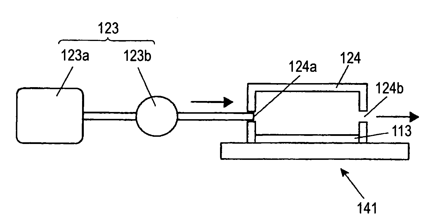
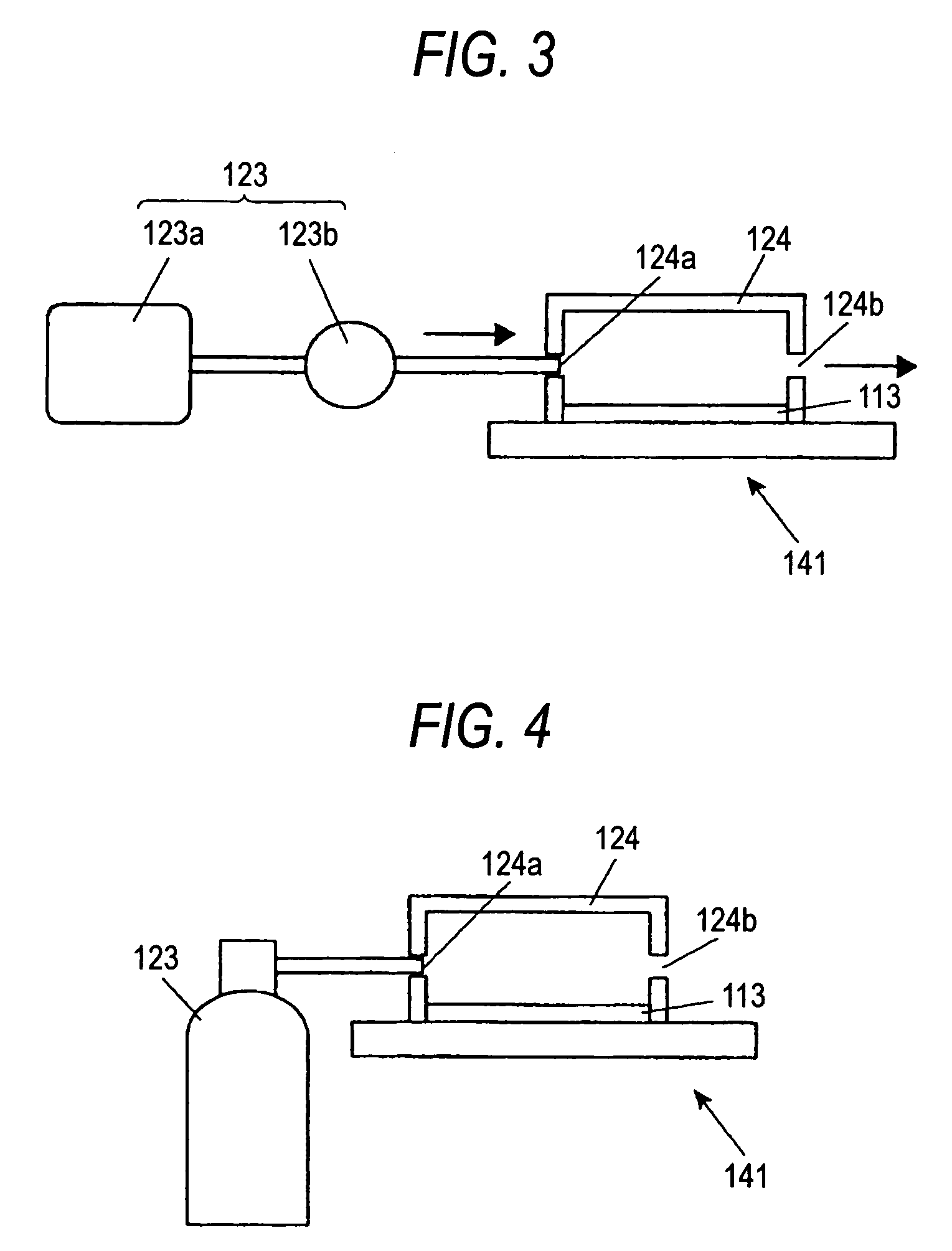
[0014]Accordingly, since the dew point in the vicinity of the piezoelectric element is lowered by the dry gas, the deterioration of the piezoelectric element caused by the voltage application can be prevented, so that reduction of the film thickness of the piezoelectric element can be achieved, and the element breaking due to the voltage application to the piezoelectric element can be readily prevented.

Problems solved by technology

By this method, it is impossible to make the area of the piezoelectric element smaller than the thickness of the piezoelectric film.
It has been known that many defects such as minute cracks and pores exist in the piezoelectric element.
In a case where the piezoelectric element is thin, a large defect passing through the element is produced by a break, so that such disadvantage is produced that an upper electrode and a lower electrode can short electrically, or the displacement property changes.
However, a high voltage must be applied in order to make the displacement large, which increases power consumption.
Further, if the film thickness is large, it becomes difficult to increase the in-plane density of the element.
According to the second method, if the piezoelectric element is sealed, the sealing work must be performed in a low humidity environment where little moisture is present, which requires much labor in the case of mass production in a factory and increases the manufacturing cost.
Further, since the piezoelectric element is covered with a box in order to seal the element, entry of moisture from a contact surface between the box and the element must be strictly prevented, which requires much labor and similarly increases the manufacturing cost.

Method used


Image

  • Ink jet recording apparatus
  • Ink jet recording apparatus
  • Ink jet recording apparatus

Examples


first embodiment

[0057]Embodiments of the invention will be described below with reference to FIGS. 1 to 10. In these drawings, the same members are denoted by the same reference numerals, and the overlapping description thereof is omitted.

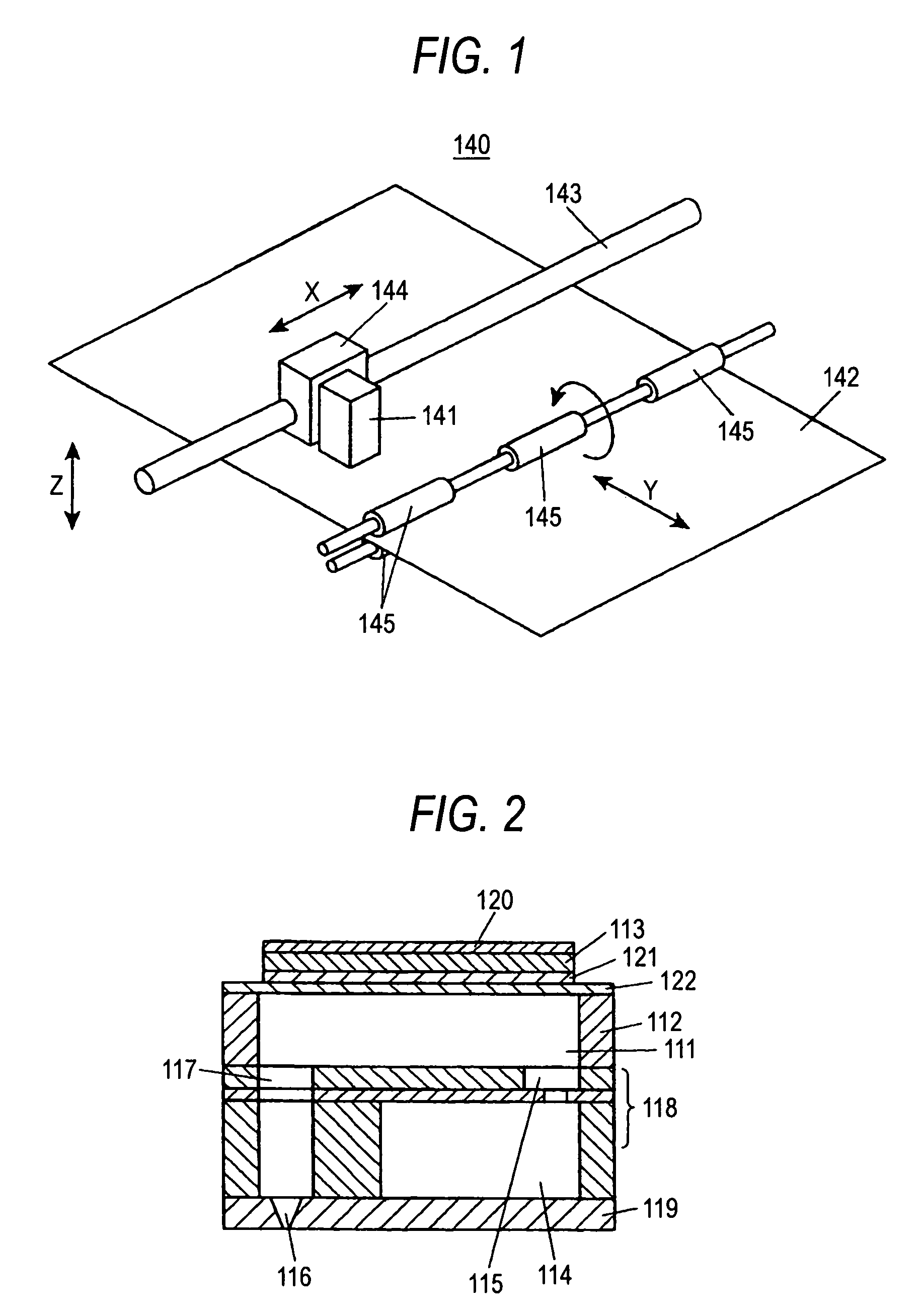
[0058]An ink jet recording apparatus 140 shown in FIG. 1 is provided with an ink jet head 141 of the invention which performs recording by use of a piezoelectric effect of a piezoelectric element that is an actuator, and impacts ink droplets ejected from the ink jet head 141 onto a recording medium 142 such as paper thereby to perform recording on the recording medium 142. The ink jet head 141 is mounted on a carriage 144 provided for a carriage shaft 143 arranged in a main scanning direction X, and reciprocates in the main scanning direction X correspondingly to reciprocation of the carriage 144 along the carriage shaft 143. Further, the ink jet recording apparatus 140 has plural rollers (moving unit) 145 which move the recording medium 142 in a sub-scanning dire...

second embodiment

[0100]Embodiments of the invention will be described below with reference to FIGS. 11 to 23. In these drawings, the same members are denoted by the same reference numerals, and the overlapping description is omitted.

[0101]An ink jet recording apparatus 240 shown in FIG. 11 has an ink jet head 241 which performs recording by use of a piezoelectric effect of a dielectric thin film element and expansion power of air bubbles and impacts ink droplets ejected from this ink jet head 241 onto a recording medium 242 such as paper thereby to perform recording on the recording medium 242.

[0102]In a case where the line head is constituted by combination of the plural nozzle heads, by characteristic unevenness between the nozzle heads and accuracy of alignment onto the nozzle head holding frame, a streak may appear in printing at a joint between the nozzle heads, so that printing quality lowers. Further, if the line head is constituted by combination of the plural nozzle heads, it is necessary t...

example 2

[0115]Here, in order to arrange the nozzle holes 247a with better space efficiency and prevent occurrence of the aforesaid warp of the nozzle plate, as shown in FIG. 18, the nozzle arrays of even numbers which are four and more are formed so that a distance between a set of nozzle arrays adjacent to each other becomes close, that is, so that the nozzle arrays come close to each other two by two. For example, as shown in FIG. 18, in the case where there are the four nozzle arrays of A to D, they are arranged so that the distance between the A array and the B array or the distance between the C array and the D array is closer than the distance between the B array and the C array.


PUM


Abstract

An ink jet recording apparatus, which performs printing by ink ejection, includes a pressure chamber in which ink liquid is filled; a nozzle hole (116) which is formed so as to communicate with the pressure chamber; a piezoelectric element (113) which is formed on the pressure chamber, and deforms the pressure chamber by mechanical expansion and contraction, whereby pressure is generated in the pressure chamber and ink is ejected from the nozzle hole (116); and a dew point control unit (123) which maintains a dew point in an atmosphere of the piezoelectric element (113) and the vicinity of the piezoelectric element at a lower value than a dew point in an environment where the ink jet recording apparatus is set. The dew point control unit (123) includes a compressor (123a), and an air drier (123b) which dries compression gas from the compressor (123a) and feeds it to the piezoelectric element.

Description

BACKGROUND OF THE INVENTION[0001]1. Field of the Invention[0002]The present invention relates to an ink jet recording apparatus which can control a dew point of air in the apparatus.[0003]2. Description of the Related Art[0004]An ink jet recording apparatus performs printing by ejecting ink of tens pico liter through many nozzle holes each having tens μm diameter onto a recording medium such as paper. An ink ejecting part comprises a nozzle plate in which many nozzle holes are provided, a pressure chamber communicating with each nozzle hole, a common liquid chamber for supplying the ink to the pressure chambers, and a unit that generates pressure in the pressure chamber.[0005]There are two types of apparatuses that generate pressure in the pressure chamber. One of them is a type in which air bubbles are generated in the pressure chamber by Joule heat, and the other is a piezoelectric type in which the pressure chamber is deformed by a piezoelectric element. In the piezoelectric type...

Claims


Application Information

Patent Timeline
Patent Type & Authority Patents(United States)
IPC IPC(8): B41J29/38B41J2/45B41J2/14B41J2/155
CPCB41J2/14233B41J2/1433B41J2/155B41J2202/20B41J2002/14475B41J2002/14491B41J2002/14362
Inventor MATSUBA, HIROYUKINAKAGAWA, TOHRUTORII, HIDEOKAMADA, TAKESHICHIKANAWA, KAZUNARINAKASHIMA, HIROAKITOMARI, SEISHI
Owner KONICA MINOLTA INC
Learn More