
Ink repellent coating on charge device to improve printer runability and printhead life

a technology of charge device and inkjet printer, which is applied in printing and other directions, can solve the problems of printhead errors, inability to print, and inability to resist debris, and achieve the effect of reducing capillary forces and high load to deflection ratio

Active Publication Date: 2007-01-02
EASTMAN KODAK CO
View PDF12 Cites 5 Cited by
  • Summary
  • Abstract
  • Description
  • Claims
  • Application Information

AI Technical Summary

Benefits of technology

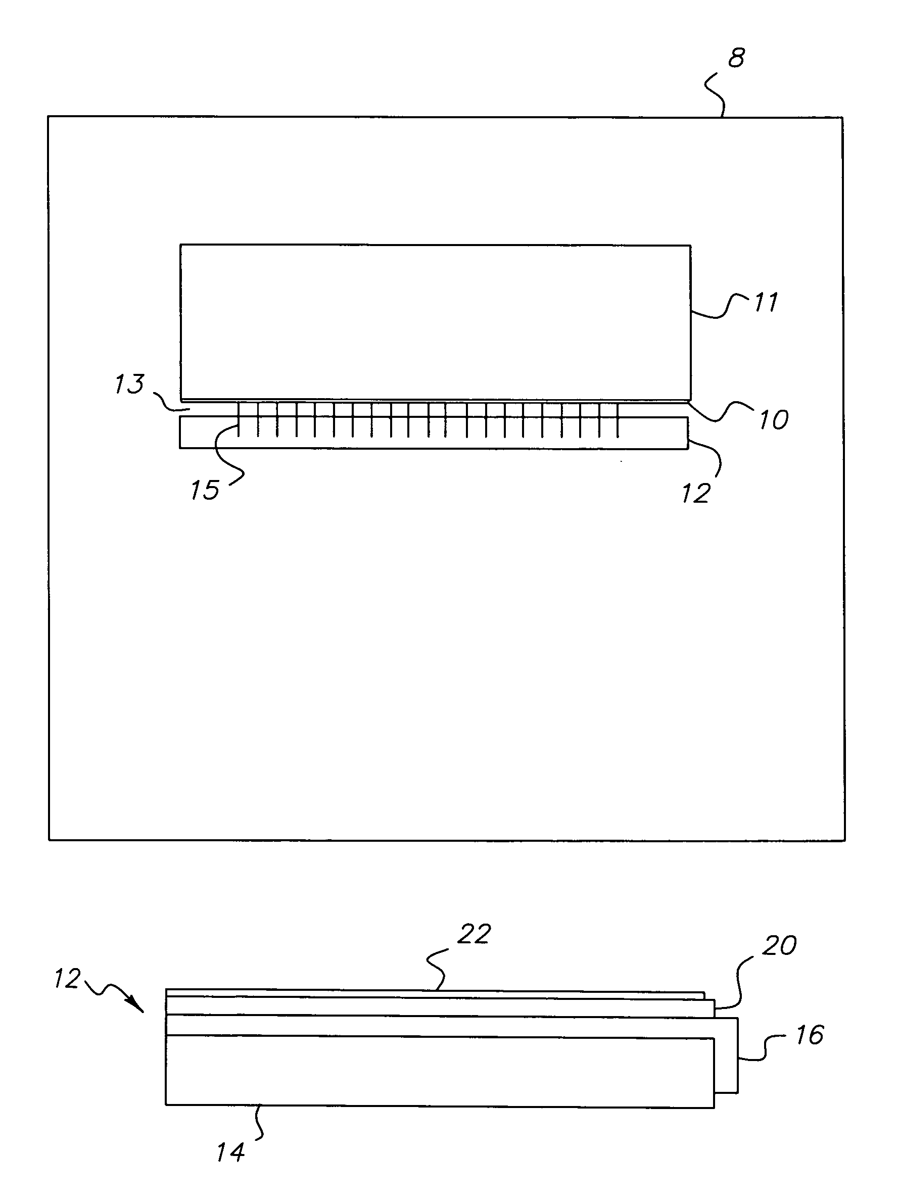
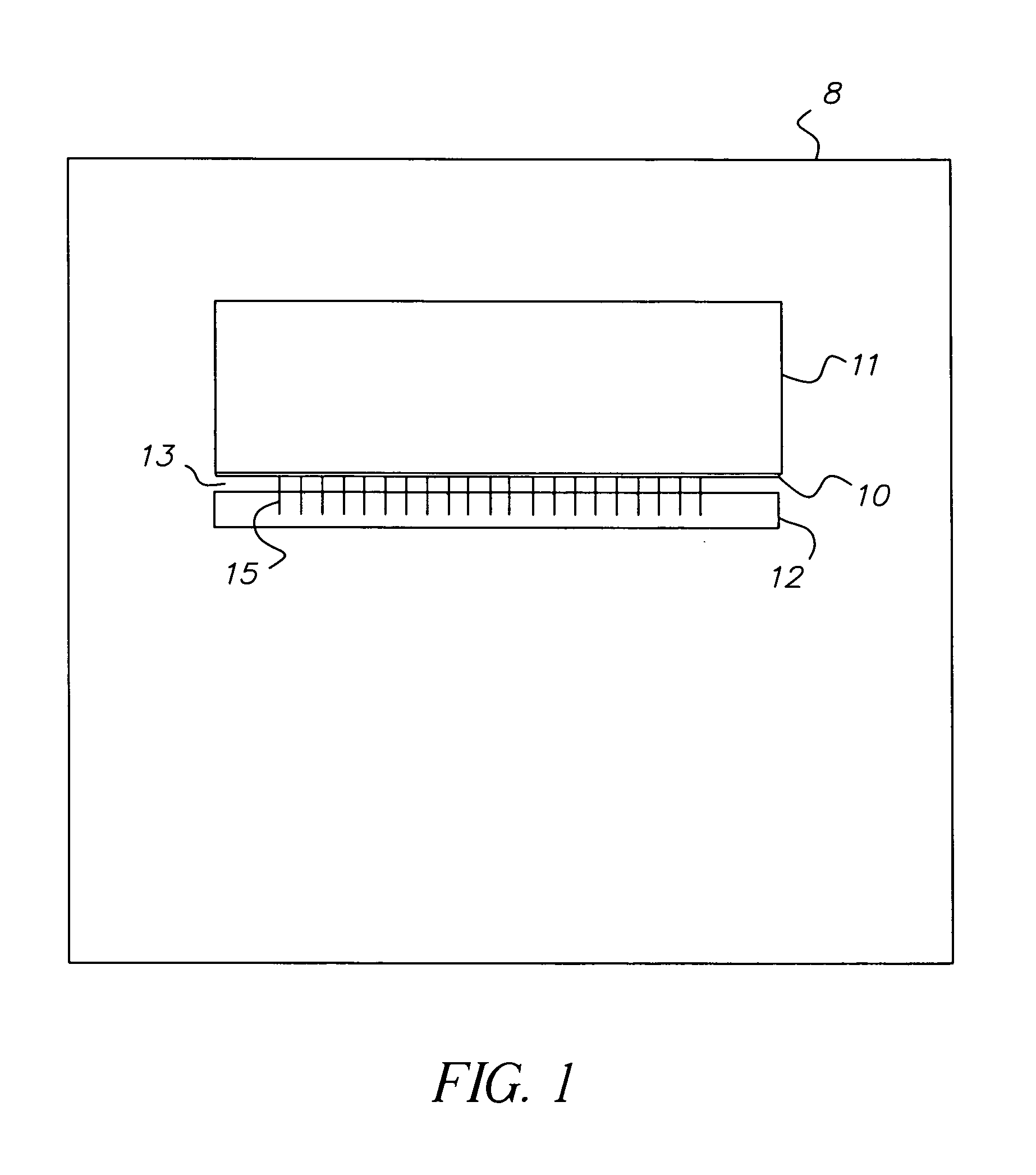
The patent describes an ink jet printhead with a special structure that reduces the forces that hold liquid in the gap between the orifice structure and the charge device. This is achieved by a coating of a non-wetting polymer that is compatible with the ink jet fluids. The technical effect of this is improved ink jet printing with reduced capillary forces, resulting in higher printing quality and efficiency.

Problems solved by technology

Ink jet printers are sensitive to the presence of debris or dried ink residues on various components.
Failure to remove ink from this space can result in electrical shorting conditions between the leads on the charge device and other leads or components in the printhead.
These types of shorting conditions often result in printhead errors and premature printhead failure.

Method used


Image

  • Ink repellent coating on charge device to improve printer runability and printhead life
  • Ink repellent coating on charge device to improve printer runability and printhead life
  • Ink repellent coating on charge device to improve printer runability and printhead life

Examples


Embodiment Construction

[0012]Before explaining the present embodiments in detail, it is to be understood that the embodiments are not limited to the particular descriptions and that it can be practiced or carried out in various ways.

[0013]The improved printhead has a charge device with a coating that results in low surface energy thereby minimizing the chance for ink to be left in a space or gap between the orifice structure and the charge device after the startup of the printhead.

[0014]The improved printhead has a coating on the charge device that enables the printhead to have a higher print quality, and an improved and more reliable start up without shorting the leads of the charge device.

[0015]This improved printhead advances the longevity of printhead operation, and improves the versatility of the printhead by increasing the printhead's ability to run different viscosity inks and different types of inks.

[0016]This improved printhead allows the printhead to have smaller orifice sizes on the orifice str...


PUM


Abstract

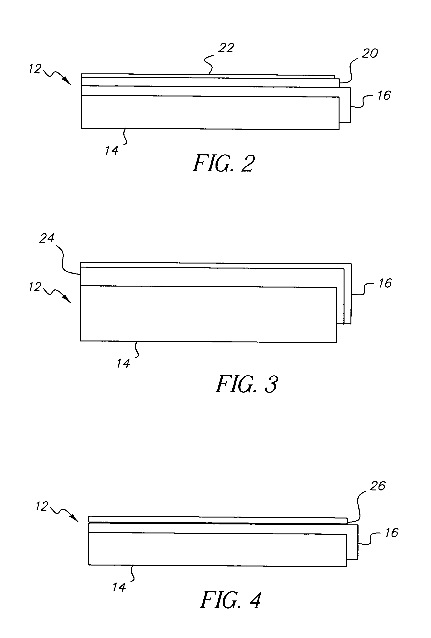
An ink jet printhead includes a drop generator having an attached orifice structure forming a jet array adapted to use ink jet fluids with a charge device disposed opposite the jet array forming a gap. The charge device includes a dimensionally stable, non-porous substrate layer having a high load to deflection ratio, one or more electrically conducting leads bonded to the substrate layer, an insulating protective layer disposed over the electrically conducting lead, and a non-wetting polymer coating compatible with the ink jet fluids disposed on the insulating protective layer. The coating reduces the capillary forces that hold liquid in the gap between the orifice structure and the charge device.

Description

FIELD OF THE INVENTION[0001]The present embodiments relate to continuous inkjet printers which employ charge devices in association with a drop generator and orifice structure.BACKGROUND OF THE INVENTION[0002]Ink jet printers are sensitive to the presence of debris or dried ink residues on various components. Various procedures have been developed for operation of the printhead which remove such contaminants from these sensitive components. When printheads have reduced orifice sizes, desirable for higher quality color printing, the operations for removing contaminants from sensitive components can leave ink in the space between the charge device and the orifice structure. Failure to remove ink from this space can result in electrical shorting conditions between the leads on the charge device and other leads or components in the printhead. These types of shorting conditions often result in printhead errors and premature printhead failure.[0003]A need exists for a way to facilitate th...

Claims


Application Information

Patent Timeline
Patent Type & Authority Patents(United States)
IPC IPC(8): B41J2/14B41J2/135B41J2/085
CPCB41J2/085
Inventor MORRIS, BRIAN G.KATERBERG, JAMES A.
Owner EASTMAN KODAK CO
Learn More